EasyManuals Logo

Eaton C441U User Manual

Eaton C441U
68 pages
To Next Page IconTo Next Page
To Previous Page IconTo Previous Page
Page #7 background imageLoading...
Page #7 background image
7
User Manual MN04200002E
Effective January 2016
C441 Ethernet module user manual
(C441R, C441T, C441U, C441V)
EATON www.eaton.com
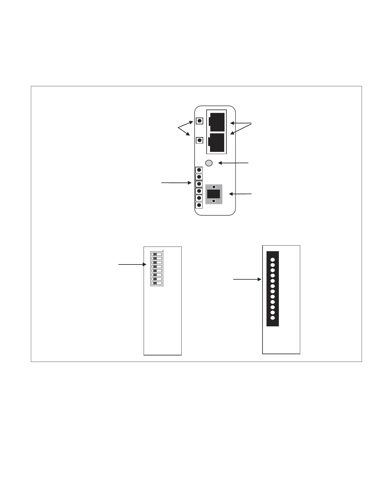
4 Connections and Switch Settings
This section describes the connections and switch settings for the
Ethernet module. The figure below depicts the connection points,
LED indicators and DIP switch settings that will be described in this
section.
Figure 4. Module Connections, Settings, and Indicators
P1
P2
Ethernet Ports (2)
RS485 Port
(Modbus)
Configuration
Reset
I/O
Indicators
Status
Indicators
Front View
Top
IP Address
Switch
Bottom
I/O and
Supply

Questions and Answers:

Question and Answer IconNeed help?

Do you have a question about the Eaton C441U and is the answer not in the manual?

Eaton C441U Specifications

General IconGeneral
Product NameEaton C441U
CategoryControl Unit
ManufacturerEaton
Input Voltage24V DC
Protection ClassIP20
DisplayLCD
Relay Outputs2
Digital Inputs4
Analog Inputs2
Mounting TypeDIN Rail
Operating Temperature-25°C to 70°C
Weight0.2 kg
Communication PortsModbus RTU, Ethernet
MountingDIN rail

Related product manuals