INM 5500 Rev 11
21
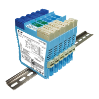
6.1.4 MTL5510 & MTL5510B - Switch/Proximity detector interface
4-channel, digital input and multifunction modules
These digital modules provide solid state output switches in a safe area that respond to switches
(inputs) located in a hazardous area. The way they respond - their “mode” - can be configured using a
bank of four DIL selector switches accessible through the side of the module - see Figure 6.4.
Model MTL5510 has an one output channel for each input channel and the user can reverse the
output phase if necessary to suit the application. Model MTL5510B has more varied modes that can,
for example, enable one input to affect multiple outputs or create latched outputs, etc.)
The channel
output transistors - Ch1/Ch2 and Ch3/Ch4 - share a common terminal and can switch +ve or –ve
polarity signals.
Note that and parallel resistors are required for switch inputs with LFD - see Section 6.1.2 for
recommended values.
Hazardous area
B
–
+
–
–
+
–
D
C
A
1
2
3
4
6
5
4
3
2
1
7
8
9
10
11
12
13
14
Safe
are
a
Terminal Function
1 Input channel A
2 Input channel AB common (+)
3 Input channel B
4 Input channel C
5 Input channel CD common (+)
6 Input channel D
7 Output channel 4
8 Output channel 3/4 common
9 Output channel 3
10 Output channel 2
11 Output channel 1/2 common
12 Output channel 1
13 Supply –ve
14 Supply +ve
Figure 6.3:
Top labels for
MTL5510
& MTL5510B

 Loading...