For more information visit: www.eatonelectrical.com IB01602009E
Instruction Booklet
Page 8 Effective: April 2006
ATC-300 Automatic
Transfer Switch Controller
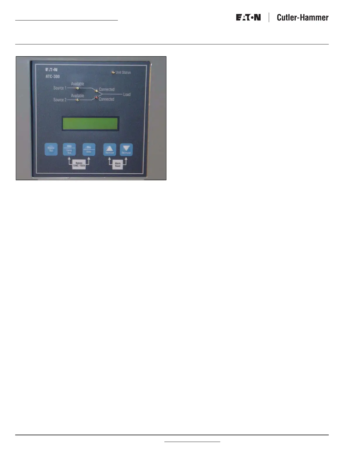
Figure 1. The ATC-300 Controller Front Panel.
2.2.1 The Output Function Components
The Display
A 2-line, 16-character alphanumeric LCD Display module is used
to display all ATC-300 Controller monitored parameters, set-
points, and messages in easy to read formats. The display has a
green high contrast background that allows clear visibility of any
information displayed. The display is continuously lit for clear vis-
ibility under poorly lit or no light conditions.
Six different displays can be presented via the LCD Display:
• Status Display
• Source 1 Display
• Source 2 Display
• Time/Date Display
• History Display
• Setpoints Display
As a default when there are no active commands or timers being
displayed, the display shows information from the source that is
connected to the load. This is referred to as the “Home” screen.
Line 1: Source 1 or 2 Metered Voltage
Line 2: Date Time
Example: Source 1 480V
1/20/06 3:35PM
See Section 3 for more detailed information.
The LEDs
Unit Status
The green Unit Status LED blinks at a rate of once per second
while in the ATC-300 Controller is in the “Run” Mode. This indi-
cates that the ATC-300 has completed a self-diagnostic and sys-
tem diagnostic cycle. The self-diagnostic cycle checks include
the:
• Microprocessor operation and
• Memory operation.
The system diagnostic cycle checks include the:
• Output relay operation;
• Control input operation; and
• Transfer switch operation.
The Unit Status LED blinks at an increased rate while the ATC-
300 Controller is in the “Program” Mode.
Source 1 Available
The white Source 1 Available LED illuminates if the Source 1
power source meets the criteria to be considered “available”.
That is, when it is within its undervoltage/overvoltage/underfre-
quency/overfrequency/voltage unbalance/phase reversal (if appli-
cable) setpoint ranges for the nominal voltage and frequency
setting.
Source 1 Connected
The green Source 1 Connected LED illuminates when the Source
1 switching device and its associated position indicating auxiliary
contact are closed.
Source 2 Available
The amber Source 2 Available LED illuminates if the Source 2
power source meets the criteria to be considered “available”.
That is, when it is within its undervoltage/overvoltage/underfre-
quency/overfrequency/voltage unbalance/phase reversal (if appli-
cable) setpoint ranges for the nominal voltage and frequency
setting.
Source 2 Connected
The red Source 2 Connected LED illuminates when the Source 2
switching device and its associated position indicating auxiliary
contact are closed.
2.2.2 The Input Function Components
The Pushbuttons and Combinations
Help/Lamp Test Pushbutton
The Help/Lamp Test pushbutton serves two functions. If the
Help/Lamp Test pushbutton is pressed when a message is
present on the LCD Display, a detailed description of the message
will appear. The detailed message description will scroll across
the bottom of the display. The detailed description can be
aborted by pressing Help/Lamp Test key a second time.

 Loading...


