Page
6
For an MDL
-
frame, also screw in and torque the load end
screws to 6
-
8 Ib
-
ft. (8.14
-
10.85 N.m.)
3.5
Final Installation Instructions (All Trip Units)
Install accessory(ies),
if
required, using the appropriate
instruction leaflet listed in Section 8.2. Where accessories
are not required, install protective barriers supplied with
the trip unit in accessory retaining slots in left
-
and right
-
hand poles of trip unit and in fourth pole current sensor
if
applicable.
Make sure interphase barriers and sliding handle barrier
are in place.
Install circuit breaker covers and pan
-
head screws as
shown in Fig.
9.
a
CAUTION
THE RATING PLUG MECHANICALLY INTERLOCKS
NIT. IF THE
Replace Term.
Cover
.164-32 x
Pan
-
head
Screw
@
$3
Fourth
until the arrow points to ENGAGED. If an adjustable rating
plug is used, four continuous current settings are possible.
Set the switch marked A, B, C, D to the current rating
desired.
Note: The reverse procedure is
used to remove the
rating plug. Turn the Push
-
to
-
Trip button to the
remove position. This action will cause the circuit
breaker to trip. Then grasp the lip of the Push
-
to
-
Trip
button and gently pull. A small screwdriver placed
under the left edge of the rating plug will assist in
removal.
Reset circuit breaker by moving handle to the reset
position. Move handle to the
ON
position. Circuit breaker
handle should remain at the
ON
position.
Press Push
-
to
-
Trip button (in rating plug) to check manual
tripping of the circuit breaker.
Fig.
9
Cover Screw
Installation Positions
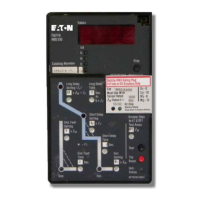
Note: Before attempting to install the rating plug, the
arrow
in
the Push
-
to
-
Trip button portion of the plug
must be pointing toward the REMOVE
position.This
can be done with a small screwdriver.
Install rating plug. Position the rating plug as shown in Fig.
10. Insert the rating plug in the trip
unit.The pins and
plunger must align correctly with the matching receptacles
and slot in the trip unit. After the rating plug is pressed into
position, depress the Push
-
to
-
Trip button with a small
screwdriver and turn it clockwise one quarter of a turn
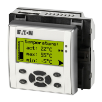
However, the trip unit contains thermal temperature
protective circuitry that initiates a trip operation for self
-
protection if the internal ambient temperature at the
printed circuit board (PCB) reaches approximately 100°C.
This may occur for open air temperatures above 40°C
with circuit breaker currents near full load.
Effective
March 2003
ambient temperatures over a range of -20º to +55ºC.
The calibration of the trip unit is insensitive to
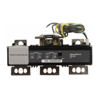
50°C rise at properly sized and installed terminations.
Trip
Unit
Fig. 10 Installing Rating Plug
In open air at 40ºC, an L-Frame circuit breaker or an
M-Frame circuit breaker with a Digitrip RMS 310 Trip
Unit installed will carry continuously up to 600 amperes
or 800 amperes respectively without exceeding a
4.0 PRINCIPLE OF OPERATION
I.L. 29C615E
1.75 Lg.
WITH THE TRIP UNIT. IF THE RATING PLUG IS NOT
CORRECTLY INSTALLED, THE CIRCUIT BREAKER
CANNOT BE RESET OR PLACED IN THE "ON"
POSITION.
Courtesy of NationalSwitchgear.com
 Loading...