Page
7
For ambient conditions above 40°C and where the
maximum ampere rating plug has been installed, derating
of the circuit breaker frame should be considered to avoid
exceeding a safe terminal temperature operating range.
Consult Cutler
-
Hammer for recommendations.
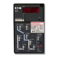
4.1 General
The Digitrip RMS 31
0
Trip Unit provides a tripping signal
to the flux transfer shunt trip when current and time delay
settings are exceeded. This is accomplished by employing
the Cutler
-
Hammer custom designed integrated circuit
SpreTMchip, which includes a microcomputer to perform
its numeric and logic functions.
In the Digitrip RMS 31
0
Trip Unit, all required sensing and
tripping power to operate its protection function is derived
from the current sensors in the circuit breaker. The
secondary currents from these sensors provide the
correct input information for the protection functions, as
well as tripping power, whenever the circuit breaker is
carrying current. These current signals develop analog
voltages across the appropriate calibrating resistors.
The microcomputer, in cyclic fashion, repeatedly scans
the voltage values across each calibrating resistor and
enters these values into memory. These data are used to
calculate true RMS current values, which are then repeat
-
edly compared with the protection function settings and
other operating data stored in the memory. The software
program then determines whether to initiate protection
functions, including tripping the breaker through the flux
transfer shunt trip device in the circuit breaker.
4.2 Overload Trip:
In accordance with standards require
-
ments, the trip unit initiates a trip of the circuit breaker
within two hours for an overload of 135 percent, and will
trip in less time for higher overload currents.
A
“Thermal Memory” effect prevents the breaker from
being re
-
energized immediately after an overload.
A
“cooling off” period of up to
5
minutes is required, which
allows time for cabling to cool off.
4.3 Short Delay InstantaneousTrip:
For short circuit
conditions that exceed the short delay pick
-
up settings,
the trip unit initiates a trip after a delay prescribed by the
I2t ramp function for trip units with catalog number suffixes
LS, LSE, LSP, and LSG.
A
flat response time delay action
is provided by trip units with catalog number suffixes LSI,
LSIE,
LSIP, and LSlG unless the instantaneous
(I)
setting
is selected.
4.4 Ground Fault Protection:
When selected, ground
fault pick
-
up and time delay settings shown in Table 1
-
2
allow selective ground fault coordination with other circuit
protection devices.
Effective
March 2003
I.L. 29C615E
CAUTION
5.0 PROTECTION SETTINGS
5.1 General
Prior to placing any circuit breaker in operation, each trip
unit protection setting must be set to the values specified
by the engineer responsible for the installation. The
available settings along with the effect of changing the
settings are illustrated in Figures 12-1 to 12-3.
The installed rating plug establishes the maximum
continuous current rating (I,) of the circuit breaker. Short
delay current settings are defined in multiples of I,.
One to four time and pick-up adjustment settings are
available depending on the particular trip unit purchased.
A rotary switch is provided for each setting. The rotary
switch is adjusted using a small flatblade screwdriver
(Figure 11).
A green status light on the face of the trip unit
indicates the operational status of the trip unit. If
the load current through the circuit breaker exceeds
approximately 20% of the maximum current rating
of the trip unit, the status light will blink on and off
once each second. A blinking status light is an
indication of a properly functioning trip unit. If the
status light is not blinking, the current through the
breakers may be less than 20% of the maximum. If
the current exceeds 20% and the status light is not
blinking, use the STK2 test kit to investigate (see
section 6.1).
MESxxxLSI, and -LSIG, Instantaneous Pickup is achieved
For catalog number LESxxxLSI, -LSIG, -LSIP, -LSIE,
5.4 Instantaneous Pickup Setting
with no intentional delay (Instantaneous).
(see Figure 12-2). The "I" setting gives a trip response
response. Four settings (I, .1, .2, .3 second) are available
MESxxxLSI, and -LSIG, the short time delay is a flat
For catalog number LESxxxLSI,-LSIG, LSIP, -LSIE,
5.3 Short Delay Time Settings
Digitrip RMS 31 0 Trip Units.
shown in Figure 12-1. This feature is included on all
Seven settings are available that range from 2 to 8 (I,) as
5.2 Short Delay Pick-Up Setting
LACK OF ILLUMINATION OF THE STATUS LIGHT
DOES
NOT
INDICATE THE TERMINALS OF THE
BREAKER ARE DEENERGIZED.
trip current involved.
configuration with the actual time delay a function of the
For catalog number LESxxxLS,-LSG,-LSP,-LSE,
MESxxxLS and -LSG the short time delay is an I²t ramp
Courtesy of NationalSwitchgear.com
 Loading...