EasyManua.ls Logo

Eaton Digitrip RMS 310 User Manual

Eaton Digitrip RMS 310
12 pages
To Next Page IconTo Next Page
Page #1 background imageLoading...
Page #1 background image
Instructions for Digitrip RMS
310
Trip Unit For Use with
R
-
Frame Breakers
TABLE
OF
CONTENTS
Description Page
1.0 General Information..
.....................
1
1.1 Protection..
.............................
1
1.2 Testing..
..............................
.2
2.0 UL Listed Devices
.......................
.2
3.0 Principle of Operation.
.....................
2
3.1 General..
..............................
.2
3.2 OverloadTrip
............................
2
3.3 Short
Delayhstantaneous Trip
..............
2
3.4 Ground Fault Protection.
...................
3
4.0 Protection Settings
.......................
3
4.1 General
................................
3
4.2 Short Delay Pick
-
up Settings
................
3
4.3 Short Delay Time Settings
..................
3
4.4 Instantaneous Pick
-
up
.....................
3
4.5 Ground Fault Pick
-
up Setting
...............
3
4.6 Ground Fault Time Setting
.................
3
6.0 Frame Ratings and Ratings Plugs
............
5
7.0 Reference..
............................
.5
7.1 Digitrip RMS Trip Assemblies.
...............
5
7.2 R
-
Frame Molded Case Circuit
Breakers
.............................
.5
5.0
Testing
................................
.5
a
WARNING
DO NOT AlTEMPT TO INSTALL
OR
PERFORM MAIN
-
TENANCE ON EQUIPMENT WHILE IT
IS
ENERGIZED.
DEATH, SEVERE PERSONAL INJURY,
OR
SUBSTAN
-
TIAL PROPERTY DAMAGE CAN RESULT FROM CON
-
TACT WITH ENERGIZED EQUIPMENT. ALWAYS
VERIFY THAT NO VOLTAGE
IS
PRESENT BEFORE
PROCEEDING WITH THE TASK, AND ALWAYS FOL
-
LOW GENERALLY ACCEPTED SAFETY PROCE
-
DURES.
THE
CUTLER-HAMMER
IS NOT LIABLE
OF ITS PRODUCTS.
The user is cautioned to observe all recommendations,
warnings, and cautions relating to the safety of personnel
and equipment as well as all general and local health and
safety laws, codes, and procedures.
FOR THE MISAPPLICATION
OR MISINSTALLATION
The recommendations and information contained herein
are based on Cutler
-
Hammer experience and judgement,
but should not be considered to be
all-inclusive or cover
-
ing every application or circumstance which may arise. If
any questions arise, contact Cutler
-
Hammer for further
information or instructions.
1
.O
GENERAL INFORMATION
1.1
Protection
The Digitrip
RMS
31
0,
illustrated in Figure 1, is an elec
-
tronic trip unit that incorporates a microprocessor
-
based
custom application specific integrated circuit design for
use with R
-
Frame Molded Case Circuit Breakers.
Fig.
1
Digitrip
RMS
310
Trip
Unit for use with R
-
Frame
Circuit Breakers
The Digitrip
RMS
310 provides true RMS current sensing
for proper correlation with thermal characteristics of con
-
ductors and equipment. Interchangeable rating plugs are
provided to establish the continuous current rating of
each circuit breaker.
Effective
February 2006
Supersedes I.L. 29C883C dated July 2003
I.L. 29C883E
Courtesy of NationalSwitchgear.com

Other manuals for Eaton Digitrip RMS 310

Question and Answer IconNeed help?

Do you have a question about the Eaton Digitrip RMS 310 and is the answer not in the manual?

Eaton Digitrip RMS 310 Specifications

General IconGeneral
Frequency50/60 Hz
CategoryElectronic Trip Unit
Voltage Rating690 V
Protection FunctionsGround Fault
CommunicationModbus
FunctionsProtection
ProtectionGround Fault
DisplayLCD
StandardsIEC 60947-2

Summary

General Information

Protection

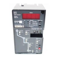
Describes the Digitrip RMS 310 as an electronic trip unit with a custom application specific integrated circuit design.

Testing

Test points are provided for functional field testing of the trip unit when connected to a test kit.

UL Listed Devices

States the Digitrip RMS 310 Trip Unit is listed in accordance with UL 489 Standard.

Principle of Operation

General

Explains the Digitrip RMS 310 provides a tripping signal using a microprocessor and custom ICs for numeric and logic functions.

Overload Trip

Explains the trip unit initiates a trip within two hours for 135% overload and has a 'cooling off' period after trips.

Short Delay/Instantaneous Trip

Describes trip initiation for short circuit conditions based on I2t ramp or flat response time delays.

Ground Fault Protection

Details how ground fault settings allow selective coordination and mentions an optional Automatic Trip Relay (ATR).

Protection Settings

General

Explains that the rating plug sets the maximum continuous current and settings are multiples of In.

Short Delay Pick-up Setting

Seven available settings ranging from 2 to 8 multiples of the rating plug amperes (In).

Short Delay Time Settings

Details I2t ramp configuration or flat response time delays for different catalog numbers.

Instantaneous Pickup Setting

Explains how to achieve instantaneous pickup by setting Short Delay Time to 'I'.

Ground Fault Pick-up Setting

Eight settings (A-K, excluding G) corresponding to fixed ampere values for ground fault pickup.

Ground Fault Time Settings

Offers four flat response time delay settings for ground fault: instantaneous (I), 0.15, 0.3, and 0.5 seconds.

Testing

Frame Ratings and Rating Plugs

References

Digitrip RMS Trip Assemblies

Lists instruction leaflets for Digitrip RMS 310, 510, 610, and 810 Trip Units.

R-Frame Molded Case Circuit Breakers

Lists instruction leaflets and diagrams for R-Frame breakers used with Digitrip RMS Trip Units.

Related product manuals