11
WIRING
WIRING AND DIP SWITCHES
All wiring to the counter is done to rear terminal, de-pluggable connectors. Up to six
headers accept the wired connectors on the counter. All units have at least three
headers, power input, count input and control input. The relay output header is
installed in the batch control base unit and is optional for the totalizer. Any combina-
tion of two additional circuit boards with headers may be installed. These option
boards are RS 485 serial communications and analog output. The option boards
occupy specific locations in the counter and are not interchangeable. All boards are
keyed to prevent installation in the wrong location.
Disconnect all power before wiring terminals. A safety hazard exists if this
precaution is not observed. Treat all control and count inputs as hazardous
since they may carry line voltage.
A switch shall be included in the building installation:
It shall be in close proximity to the equipment and within easy reach of the
operator.
It shall be marked as the disconnecting device for the equipment.
Switches and circuit breakers in Europe must comply with IEC 947.
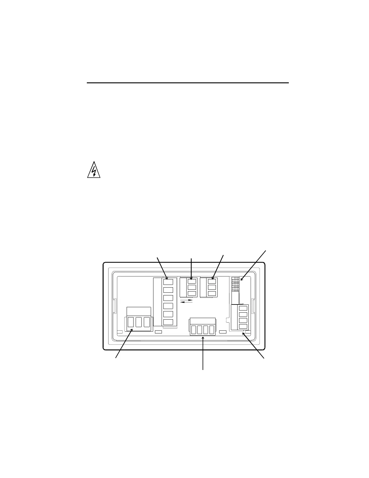
Rear Terminal Layout
1
1
1
Relay
Output
RS485
Communications
Analog
Output
DIP Switch
Count Input
Power Input
2 Terminals for DC
Powered Units
3 Terminals for
AC Powered Units
Durant
®
Control Input