13
3) Parallel installation and operation
a). Brief introduction to redundancy configurations
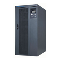
N+X is currently the most reliable power supply structure. N represents the
minimum number of UPS that the total load needs; X represents the redundant
UPS number, i.e. the fault UPS number that the system can handle
simultaneously. The bigger the X is, the higher reliability of the power system is.
For occasions where reliability is highly depended on, N+X is the optimal mode.
As long as the UPS is equipped with parallel cables, up to 3 UPSs can be
connected in parallel to realize output power sharing and power redundancy.
b). Parallel installation
★ Users need to prepare a standard 25-pin communication cable, which should
have 25 cores, corresponding stitches and shield, for communication of the
parallel system. The length of the parallel cable is appropriate to be less than
3m. (this should be corrected, as Santak makes available both 5m and 10m
cables)
★ Strictly follow the stand-alone wiring requirement to perform the input wiring of
each UPS.
★ Connect the output wires of each UPS to an output breaker panel.
★ Disconnect the Jumper between JP1 and JP2 of the terminal block first, and
connect each output breaker to a main output breaker and then to the loads.
* The requirement of the output wiring is as follows:
★ When the distance between the UPSs in parallel and the breaker panel is less
than 20 metres, the difference between the total length of input & output cables
between each UPS unit is required to be less than 20%.
★ When the distance between the UPSs in parallel and the breaker panel is more
than 20 metres, the difference between the total length of input & output cables
between each UPS is required to be less than 10%.
 Loading...