1. ELC Concepts
MN05003003E For more information visit: www.eaton.com
1-17
1.8 Basic Program Design Examples
The examples that follow illustrate how common functions can be programmed.
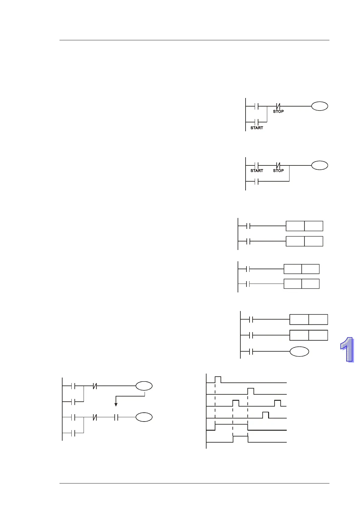
Example 1 - Stop First latched circuit
When X1 (START) = ON and X2 (STOP) = OFF, Y1 will be ON.
If X2 is turned on, Y1 will be OFF. This is a Stop First circuit
because the STOP button has the control priority over the
START button.
X2
Y1
X1
Y1
Example 2 - Start First latched circuit
When X1 (START) = ON and X2 (STOP) = OFF, Y1 will be ON
and latched. If X2 is turned ON, Y1 remains ON. This is a Start
First circuit because the START button has the control priority
over the STOP button.
X2
Y1
X1
Y1
Example 3 - Latched circuit using SET and RST
X2
Y1
X1
SET
Y1
RST
Stop first
The diagrams are latched circuits using the RST and SET
instructions.
The instruction encountered last in a program will determine the
final state of Y1. Therefore, if both X1 and X2 are ON and the
RST instruction is after the SET instruction, this forms a Stop
First circuit. Conversely, if the SET instruction is after the RST
instruction, this forms a Start First circuit.
X2
Y1
X1
SET
Y1
RST
Start first
Example 4 - Power down latched circuit
The auxiliary relay M512 is a latched relay. Once X1 is ON, Y1
retains its status before power down and resumes after power
up.
X2
M512
X1
SET
RST M512
Y1
M512
Example 5 - Conditional Control
X3
Y1
X1
Y1
X4
Y2
X2
Y2
Y1
X1
X3
X2
X4
Y1
Y2
Because NO contact Y1 is connected to the circuit of Y2 output, Y1 becomes one of the conditions
for enabling Y2, i.e. for turning on Y2, Y1 must be ON
 Loading...


