Do you have a question about the Eaton ELC-PB and is the answer not in the manual?
Explains the ELC scan cycle: reading inputs, evaluating the program, and refreshing outputs.
Explains how current flows through ladder logic paths and the concept of reverse current.
Defines normally open (NO) and normally closed (NC) contacts used in ladder logic.
Introduces basic ELC internal devices like X (Input), Y (Output), M (Internal), S (Step), T (Timer), C (Counter), D (Data), E/F (Index) registers.
Details ladder diagram symbols, their explanations, instructions, and available devices.
Explains the process of converting ladder diagrams to instruction list mode and vice versa.
Provides methods for improving ladder logic, simplifying programs, saving memory, and enhancing scan time.
Illustrates common programming functions like latched circuits, SET/RST usage, and conditional control logic.
Details the memory map, specifications, and remarks for ELC-PB/ELCB-PB controllers, including I/O, relays, timers, and counters.
Details the memory map, specifications, and remarks for ELC-PC/PA/PH controllers, including I/O, relays, timers, and counters.
Details the memory map, specifications, and remarks for ELC-PV controllers, including I/O, relays, timers, and counters.
Details the memory map, specifications, and remarks for ELCM-PH/PA controllers, including I/O, relays, timers, and counters.
Explains the latched memory settings for PC/PA/PH controllers, detailing general, latched, and special auxiliary relay configurations.
Describes the various modes for latched memory (e.g., Power OFF, STOP=>RUN) in ELC controllers.
Explains the different numeric types (bit, nibble, byte, word, double word) utilized in ELC instructions and their relationships.
Explains the different numbering systems (BIN, OCT, DEC, BCD, HEX) that ELC controllers can use.
Details the functions and compatibility of special M relays across various ELC models for system operations.
Describes S relays and their specific roles in Sequential Function Chart (SFC) programming.
Explains timer instructions, their resolution units (ms), counting methods, and how preset values affect output coils.
Explains counter instructions, including 16-bit and 32-bit high-speed counters, their types, ranges, and operations.
Details high-speed counter specifications, input configurations, counting modes, and maximum frequencies for various ELC models.
Explains special D registers, their functions, and model-specific variations for system data.
Explains index registers and their function as modifiers for accessing devices and data.
Describes file registers and how to access them using MEMR/MEMW instructions or ELCSoft, noting limitations.
Explains pointers used for master control, subroutines (CJ, CALL), and interrupt handling.
Provides examples of using special M relays (operation flags) and D registers for system status and time monitoring.
Lists basic instructions with mnemonics, operands, execution speed across models, and program steps.
Provides detailed explanations and program examples for fundamental instructions like LD, LDI, AND, ANI, OR, ORI, ANB, ORB, MPS, MRD, MPP, OUT, SET, RST, MC/MCR, END, NOP, NP, PN.
Explains pointer (P) usage with jump (CJ) and subroutine call (CALL) instructions, including available ranges.
Details interrupt pointers (I) used with application commands EI, DI, IRET, and lists interrupt types supported by different models.
Introduces instructions like CJ, CMP, and explains operands and their availability across models.
Provides a comprehensive numerical list of instructions, their API numbers, functions, and availability across ELC models.
Offers in-depth explanations and examples for instructions such as CJ, CALL, FEND, IRET, EI, DI, and WDT.
Explains SFC as a graphical method for organizing PLC programs using steps, transitions, and inner ladders.
Explains SFC toolbar icons, their descriptions, and how they are used in diagrams (e.g., Common Ladder, Initial Step).
Illustrates how SFC code compiles into Instruction List and can be viewed in Ladder, detailing rules for SFC editing.
Describes the communication ports (COM1, COM2, COM3) available on ELC processor modules and their capabilities.
Details configuring communication ports for master/slave operation, transmission modes (ASCII/RTU), and data packet formats.
Explains Modbus ASCII transmission mode, including message frame structure, fields, and ASCII/Hex value conversion tables.
Explains Modbus RTU transmission mode, including message frame structure, fields, and CRC checksum calculation.
Describes how native ELC data elements (S, X, Y, T, M, C) map to Modbus addresses across different ELC models.
Lists function codes supported in slave mode, such as Read Coil Status, Read Input Status, Read Register, and Force Coils.
Lists Modbus function codes supported by ELC when acting as a master device, including MODRD, MODWR, MODRW.
Provides a table of common ELC system problems (e.g., LEDs OFF, ERROR LED flashing) and their corresponding troubleshooting and corrective actions.
Lists detected errors with hexadecimal fault codes, descriptions, and recommended actions for resolving them.
Explains error check addresses (M1067, M1068) and error codes (D1067) related to program execution and algorithm errors.
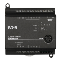
| Input Voltage | 24 VDC |
|---|---|
| Number of Inputs | 8 |
| Digital Inputs | 8 |
| Protection Class | IP20 |
| Type | Logic Controller |
| Analog Inputs | 0 |
| Analog Outputs | 0 |
| Communication Ports | RS-232 |
| Programming Language | Ladder Diagram (LD) |
| Operating Temperature | 55 °C |

