ELC Programming Manual
FOR MORE INFORMATION VISIT: WWW.EATON.COM MN05003003E
2-2
2 Programming Concepts
2.1 ELC Memory Map for ELC-PB/ELCB-PB controllers
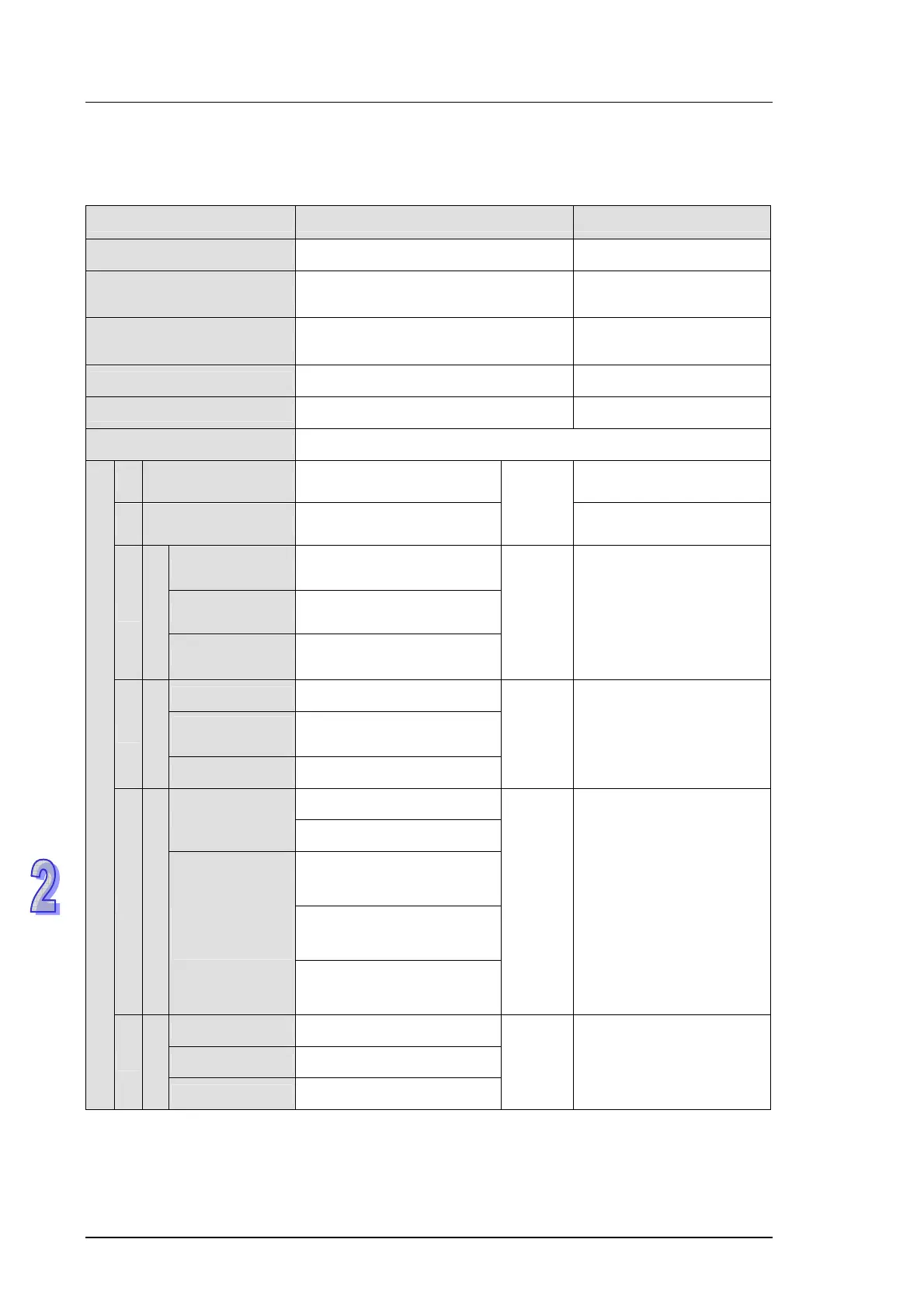
Items Specifications Remarks
Control Method Stored program, cyclic scan system
I/O Processing Method
Batch processing method
(when END instruction is executed)
Fast I/O refresh instruction
can override batch update
Execution Speed
Basic instructions – 3.5μ seconds
minimum
Application instructions
varies per instruction
Program language Instructions + Ladder Logic + SFC
Program Capacity 3792 Steps Built-in EEPROM
Instructions 32 Basic instructions, Application instructions: 109
X External inputs
X0~X177, octal number
system, 128 points max.
Physical input points
Y External outputs
Y0~Y177, octal number
system, 128 points max.
Total
256 I/O
Physical output points
General
M0~M511, M768~M999
744 points Note 1
Latched
M512~M767, 256 points
Note 3
M
Auxiliary relay
Special
M1000~M1279, 280 points,
some are latched
Total
1280 bits
Main internal relay area
for general use.
100ms T0~T63, 64 points
10ms
(M1028=ON)
T64~T126, 63 points
T
Timer
1ms T127 1 points
Total
128 bits
Contact = ON when timer
reaches preset value.
C0~C111, Note 1
16-bit count up
C112~C127, Note 3
C235~C238, C241, C242,
C244, 1 phase 1 input, 7
points Note 4
C246, C247, C249, 1 phase
2 input, 3 points
Note 4
C
Counter
32bit high-
speed count
up/down
C251, C252, C254, 2 phase
2 input, 3 points
Note 4
Total
141 bits
Contact = ON when
counter reaches preset
value.
Initial step point S0~S9, 10 points, Note 4
Zero return S10~S19, 10 points, Note 4
Bit Contacts
S
Step point
Latched S20~S127, Note 4
Total
128 bits
SFC usage
S10~S19 is used with IST
instruction
 Loading...


