5 Application examples
5.1 Single-channel controlled stop application (cat. 3, SIL 3, PL e) with error prevention
EMS2… Electronic motor starter 10/19 MN034003EN www.eaton.com 35
Figure 19: Single-channel controlled stop application with safety relay with error prevention
(disconnect U
s
)
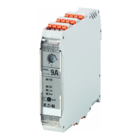
Motor starter EMS2-ROS… is used in conjunction with an ESR5-series
safety relay. The preset for the control commands for the operating direction
takes place directly at 24 V DC on the L or R terminal. In contrast to the previ-
ous example, in the case of a controlled stop, the supply voltage on the ter-
minals A1 and A2 is switched off by the safety relay.
Please also refer to Page 33 for more information about the lifespan of
devices.
L1
L2
L3
N
PE
GND
ESR5-NO-21-24 V AC-DC
24 V DC
GND
24 V DC
F1
3/
L2
1/
L1
A
2
A
1
E R L
5/
L3
2/
T1
4/
T2
6/
T3
95 96 98
M
3 ~
W1V1U1
MAN
RES
AUT
S2
S2
A1 S11 S12 S21 S22
13 23 31
A2 S33 S34
14 24 32
S3
→
Motor starter and safety relay should be located in the same
control panel.
 Loading...


