3 Plug-in motor starter ROSF for mounting on an adapter
3.1 Mounting
EMS2… Electronic motor starter 10/19 MN034003EN www.eaton.com 21
Table 7: Terminal assignment
3.1 Mounting
The EMS2 system includes two types of adapters:
• Top-hat rail adapter EMS2-XTH
The motor starter is supplied via terminals on the adapter. The adapter is
mounted on a top-hat rail and the starter is inserted into the adapter.
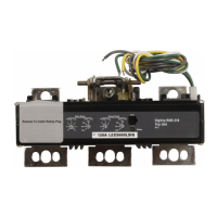
• Busbar adapter
• Classic EMS2-XBB60
Power to the busbar adapters is supplied by a busbar which runs along
the back. It is not necessary to supply the individual starters.
In addition, EMS2-ROSF motor starters are compatible with the Motor
Starter Feeder System (MSFS).
Terminal Function
1L1 three-phase incoming unit
3L2 three-phase incoming unit
5L3 three-phase incoming unit
2T1 three-phase motor connection
4T2 three-phase motor connection
6T3 three-phase motor connection
A1 control voltage connection
A2 control voltage connection
A2 is simultaneously the reference point for the control inputs ON as well
as L and R
ON Motor startup (withDOL starters)
Reference point is terminal A2
L
Motor startup in counterclockwise rotation (for reversing starters)
Reference point is terminal A2
R
Motor startup in counterclockwise rotation (for reversing starters)
Reference point is terminal A2
95
Relay output for fault messages
96 Relay output for fault messages
98 Relay output for fault messages
RES / MAN
Input for manual resetting of error messages
RES / AUT Input for automatic resetting of error messages
→
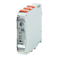
Note that a direct linking of devices with a rated operational
current I
e
of 9 A can lead to a reduction in performance (derating)
under some circumstances.
 Loading...