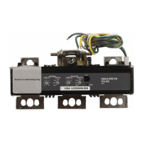
3 Plug-in motor starter ROSF for mounting on an adapter
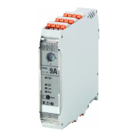
20 EMS2… Electronic motor starter 10/19 MN034003EN www.eaton.com
Figure 9: Block diagram
→
Block diagram 9 serves merely to show the general functions.
The actual wiring depends on the application case,
→ chapter 5, “Application examples”, page 33.
→
The voltages supplying the motor starter on terminals A1 and
A2 and the voltage which activates terminals R and L do not
need to originate from the same source.
Reference point for activation is terminal E.
Figure 10:Mutual (left) and separate (right)
voltage sources for supply and control inputs
2/
T1
4/
T2
6/
T3
M
3 ~
A2
E
MAN
RES
AUT
98 95 96
SET/
RESET
Reset
U
S
RL
A1 R L
ERR
L
RESET
RPWR
A2
E
U
e
RL
A1 R L
 Loading...