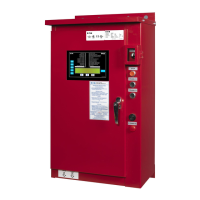
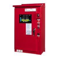
Diesel Engine
Additive (Foam) Pump Controllers
BR081012EN
April 2015
Reduced Size
A streamlined internal design has
allowed the overall size of the DIESEL
Plus controllers to be reduced from
previous models. See dimensional
drawings on our website.
Technical Speci cations
• Supply Voltage: 100-240Vac
• Output Voltage: 12-24Vdc
• Hertz: 50/60 Hz
• Enclosure:
Standard NEMA 2
• Optional NEMA 3R, 4, 4X, 12
• Temperature:
4 to +50 deg. C
39 to +122 deg. F
• Alarm Relays: DPDT 8amp
• Engine Run Relay:
DPDT 10amp
• Crank / Fuel Stop Relays: SPDT
• Pressure Transducer: 500psi
• Immunity Compliance:
Environment A
• Emission Compliance:
Environment B
Battery Chargers
• Mode: Switching
• Dual 10 Amp
• Communication to Power
I/O Board
• Diagnostics Recording
• Lead Acid or NiCadThree Step
Charge
• Internal Temperature
Monitoring
• Universal Voltage Input
• Selectable Dual Voltage Output
Standards & Certi cation
The FDF120 Diesel Engine Fire
Pump Controllers meet or exceed
the requirements of Underwriters
Laboratories, Factory Mutual
Research (FM), the Canadian
Standards Association, New York City
building code, CE mark and U.B.C. /
C.B.C Seismic requirements, and are
built to NFPA 20 standards.
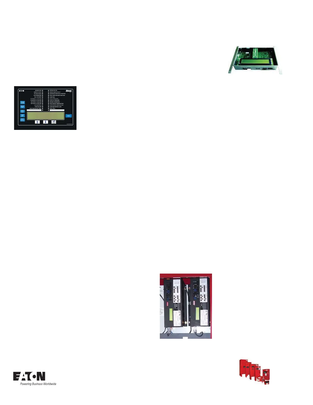
LCD Display
The Controller Display Board contains
a 4 Line by 40 Characters wide, back-
lit, LCD display which is capable of
generating multiple languages. The
display will show the current system
pressure, time and date, charger
output voltage and any custom mes-
sages, alarms or timer values.
Status LED's
The controller is supplied with six (6)
green status LED's for the following:
• LOW PRESSURE
• ENGINE RUN
• REMOTE START
• INTERLOCK ON
• DELUGE VALVE
• One Programmable LED
Alarm LED's
The controller is supplied with
twenty (20) red alarm LED's for the
following:
• BATTERY #1 FAILURE
• CHARGER # 1 FAILURE
• BATTERY #2 FAILURE
• CHARGER # 2 FAILURE
• LOW PRESSURE
• SYSTEM OVER PRESSURE
• LOW FOAM LEVEL
• LOW FUEL
• FAIL TO START
• HIGH ENGINE TEMP
• LOW OIL PRESSURE
• ENGINE OVER SPEED
• ECM SELECTOR IN ALT
POSITION
• FUEL INJECTION
MALFUNCTION
• ECM WARNING
• ECM FAILURE
• HIGH RAW WATER TEMP.
• LOW ENGINE TEMPERATURE
• FUEL SPILL
• One Programmable LED
Statistics
Up to 26 statistical points are record-
ed to provide a quick review of how
the system has been operating. The
statistics can be viewed on the main
display, saved to a USB disk drive, or
viewed on the embedded webpage.
Diagnostics
Up to fty three diagnostic points are
recorded that can be used to help
in troubleshooting issues with the
controller. The diagnostics can be
viewed on the main display, saved
to a USB disk drive, or viewed on the
embedded webpage.
Message History
Up to10k alarm/status messages can
be stored in the controller memory.
They can be viewed on the main
display, saved to a USB disk drive, or
viewed on the embedded webpage.
DC Fail
A visual indication and audible alarm
is provided to indicate DC power loss
due to one or both batteries being
disconnected from the controller.
This indication will also be provided if
the controller is not operating due to
an electronic board failure.
Programmable Features
• Languages
• (English, French, Spanish
Standard. Other languages are
available. Consult factory.)
• Date and Time
• Pressure Start and Stop Points
• Low and High Pressure Alarms
• Stop Mode
• Low Suction Shutdown
• Pressure Recording Parameters
• Run Period Timer
• Weekly Test Timer
• Sequential Start Timer
• AC Failure Alarm
• AC Fail to Start
Enclosures
Ratings
All FDF120 controllers come standard
with NEMA 2 enclosures unless oth-
erwise ordered.
Available options include:
NEMA 3R, 4, 4X, 12.
© 2015 Eaton
All Rights Reserved
Printed in Canada
Publication No. BR081012EN
April 2015
Eaton Industries Canada Company
10725 25th Street NE #124
Calgary, AB T3N0A4
Canada
www.chfire.com