EasyManua.ls Logo

Eaton FD120 User Manual

Eaton FD120
44 pages
To Next Page IconTo Next Page
Page #1 background imageLoading...
Page #1 background image
Diesel Engine
Fire Pump Controllers
Standard Output Relays
All standard output relays are 8 amp,
DPDT.
Future # 1
Future # 2
• Low Fuel
• Auto Mode
• Common Alarm
Optional Output Relays
There is provision to add up to eight
additional relay outputs, via four
optional relay output boards which
mount in a snap-on con guration.
Each board contains a maximum of 2
additional relays.
Engine Run Relay
The Power I/O Board houses a 10
Amp engine run relay which is used
for alarm purposes, or to power
external louvers.
Common Alarm Relay
The FD120 controller has a com-
mon alarm relay which de-energizes
whenever there are any alarm condi-
tions present. This relay is energized
under normal conditions and has LED
status indication.
Alarm Relay Rating
All alarm relays are rated 8 amps,
250Vac, resistive load only.
Programmable Outputs
Up to 10 additional, programmable
outputs (two standard; eight via
optional output boards) can be
programmed to indicate up to 45
output conditions. They can be pro-
grammed for fail safe and latch until
reset by the user. All optional inputs,
outputs and LED’s can be linked, as
required. They can also be pro-
grammed with time delay functions.
As well, two optional alarm LED’s can
be programmed for up to 28 alarm
conditions.
Power / Voltage
Universal Voltage Supply
The controller can be powered with
supply voltages from 100Vac to
240Vac by connecting to the three
input terminals L,N,G located on the
bottom left of the engine board.
Dual Output
12 or 24Vdc output is selectable via
a DIP Switch located on the battery
chargers. Note: Each controller is fac-
tory set for 12Vdc. If 24Vdc is required
from the factory, it should be noted
on the ordering information.
Line Filter
A line  lter incorporated onto the
engine board, is used to reduce/
eliminate external incoming voltage
transients.
AC Power Disconnect
A breaker located inside the control-
ler on the Engine Board, is used
to switch on and o AC power to
the unit. It will illuminate when
energized.
DC Power Disconnect
The engine board houses two
on-board circuit breakers used to
switch on or o DC power from the
batteries.
Each breaker has an LED mounted
on the engine board that illuminates
when the breaker is energized.
Alarm and Status
Indication
Accessibility
All alarm and status LED’s as well as
the LCD Display and programming
buttons are accessible from the front
of the controller.
Product Description
The DIESEL Plus Fire Pump
Controllers from Eaton are designed
to control and monitor 12 or 24
volt, diesel  re pump engines and
are among the most technically
advanced diesel engine controllers
available.
They are an enhanced version
of the original microprocessor-
based, FD100 Series of diesel
engine controllers. Programming is
straightforward due to the use of the
core  rmware and menu structure
utilized in the LMR Plus Series of
electric controllers.
The controller can be ordered with
the option to display and output
current values and status, on
command, from various software
protocols.
An embedded web page for
retrieving diagnostics and history
reports, can be accessed from the
optional Ethernet communication
port. An optional RS485 serial port
can be used for direct connection to
a computer for data transfer.
Product Features
Communication
Embedded Web Page
The embedded web pages allow the
user to view the current status of
the controller as well as all amper-
age readings, set points, diagnostics,
statistics, con guration and history.
An external computer connected via
the optional ethernet port is used to
access the pages. The speci c data
required can be downloaded for
reference purposes.
Communication Types
USB
The USB port is used to download the
controller message history, statistics,
diagnostics, status and con guration
data to a USB disk drive. The USB
port can also be used to upload cus-
tom messages, additional languages,
and update the microprocessor
rmware.
Ethernet
An external computer can commu-
nicate with the Diesel Plus controller
via the optional ethernet port. An
embedded web page will display
the controller’s current status, as well
as display all current readings, set
points and history.
Modbus
The Diesel Plus  re pump control-
lers have the option to communi-
cate to systems using the Regular
level of Modbus (includes both RTU
and ASCII transmission modes).
Communication settings are user
con gurable through the Diesel Plus
con guration menu.
Field Connections
Standard Inputs
• Remote Start
• Fuel Spill
• Deluge Valve
• Low Suction
• Interlock On
• Pump Start
• Low Fuel
Programmable Inputs (9)
Programmable Inputs
Up to 9 additional, programmable in-
puts can be programmed to indicate
up to 13 di erent types of inputs.
They can be programmed to energize
the common alarm output, link to
relays and optional LED’s and latch
until reset by the user.
All optional inputs, outputs and LED’s
can be linked, as required. They can
also be programmed with time delay
functions.
FD120 Diesel Engine ControllersE ective April 2015BR081011EN

Table of Contents

Question and Answer IconNeed help?

Do you have a question about the Eaton FD120 and is the answer not in the manual?

Eaton FD120 Specifications

General IconGeneral
BrandEaton
ModelFD120
CategoryController
LanguageEnglish

Summary

Product Description

Product Features

Details the capabilities and components of the DIESEL Plus controller.

Power and Voltage Specifications

Covers power supply requirements, voltage options, and protection features.

Alarm and Status Indication

Describes how the controller indicates alarms and system status.

Controller Interface and Indicators

LCD Display Features

Details the 4-line, 40-character backlit LCD display capabilities.

Status and Alarm LEDs

Explains the function of green status and red alarm LEDs.

System Data and Configuration

Data Logging Capabilities

Covers statistics, diagnostics, and message history storage.

Programmable Features

Lists configurable options like languages, timers, and inputs/outputs.

Technical and Physical Specifications

Enclosures and Ratings

Describes enclosure types (NEMA) and ratings.

Technical Specifications

Lists supply voltage, frequency, temperature, and certifications.

Battery Chargers

Details the dual 10 Amp battery chargers and their functions.

Field Connections Overview

Engine Board Terminal Blocks

Details input and output terminals on the engine board.

Technical Data and Specifications

Provides wire size recommendations for terminals and distances.

Wire and Cable Specifications

LMR Plus Electric Controller Wiring

Details cable sizes for LMR Plus controller connections.

DIESEL Plus Controller Wiring

Specifies wire sizes for DIESEL Plus controller terminals.

Product Options Selection

Language Options

Lists available language settings for the controller.

DIESEL Plus Controller Options

Lists various optional features and configurations available for the controller.

Typical Specifications Overview

Approvals and Certifications

Lists standards and approvals the controller meets.

Controller Construction

Describes internal component mounting, wiring, and battery chargers.

Pressure Sensor and Output Relays

Details pressure sensing and the types of output relays provided.

Enclosure and Microprocessor Control

Covers enclosure types and programmable microprocessor parameters.

Controller Interface and Features

LCD Display and LED Indicators

Details the LCD screen and status/alarm LEDs on the operator panel.

Microprocessor Board Features

Explains capabilities like USB, Ethernet, RS485 ports, and embedded web page.

Controller Operation Modes

Covers specific operational aspects like Fail-to-Start alarms and timers.

Advanced Controller Features

Shutdown and LED Testing

Details low suction shutdown functionality and LED testing.

Programming Menu Structure

Outlines the organization of the controller's programming menu.

Custom Inputs and Outputs

Explains how to configure custom inputs, outputs, and LEDs.

Front Operator Panel Details

LCD Display Functionality

Describes the seven different displays available on the LCD.

Status and Alarm LED Functions

Explains the meaning and behavior of all status and alarm LEDs.

Pushbutton Functions

Details the operations of the control panel pushbuttons.

Introduction and Safety

Safety Information

Covers general safety, precautions, and warnings for installation and operation.

Product Overview

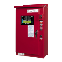
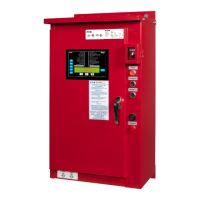
Introduces the DIESEL Plus Controller as a multi-function microprocessor unit.

Installation and Connections

Mounting and Pressure Sensor

Details controller mounting requirements and pressure sensor connections.

Electrical Connections

Provides guidelines for making electrical connections, including conduit and wiring standards.

Hardware Description

General Hardware Overview

Introduces the controller hardware and its components.

Battery Charger Details

Explains the operation and features of the three-step battery chargers.

Front Operator Panel

Describes the accessibility and functions of the front operator panel.

Battery Charger and Front Panel Details

Charger Setup and Protection

Covers AC input fuse protection, charger setup, and forced charging.

Charger Specifications

Lists technical specifications for the battery chargers.

Front Panel Functions

Details the functions of the front operator panel, including alerts and manual start.

Operator Panel Components

LED Indicators and Pushbuttons

Explains the function of all LEDs and control pushbuttons on the panel.

Display Board and I/O Board

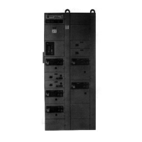
Describes access to the display board and the function of the Power I/O Board.

Engine Board and External Controls

Details the Engine Board and external pushbuttons like stop.

Controller Operation Modes

Stop Pushbutton Function

Explains the function of the stop pushbutton.

General Operation and Start Sequences

Covers manual and automatic start sequences and program descriptions.

Control Inputs Overview

Details the available control inputs and their descriptions.

Operation Details

Timers and Alarm Descriptions

Explains Run Period Timer, Sequential Start Timer, and various alarms.

Output Relays and Engine Alarms

Details output relay functions and specific engine alarm conditions.

Programming Introduction and Navigation

Covers the basics of controller programming and menu navigation.

Timer and Input Configurations

Run Period and Sequential Timers

Explains the functionality and programming of RPT and SST.

Control Input Descriptions

Details the states and operations of various control inputs.

Alarm Functions and Outputs

Controller Alarms and Failures

Describes alarms for DC power loss, speed switch, starter coils, and power failures.

Output Relay Functions

Explains the functions of engine run, future relays, and common alarm relays.

Engine Alarm Conditions

Details specific engine alarms like Overspeed, Fail To Start, and High Temperature.

Programmable Features and Set Points

Pressure Settings Configuration

Details configuration for pressure sensor, start/stop points, and alarms.

Timer Values Configuration

Covers programming for RPT, Weekly Test Timer, AC Power Failure, and SST.

Custom I/O and Password Settings

Explains configuration for custom inputs/outputs, lights, and main menu password.

Advanced Programmable Settings

Shutdown and Pressure Settings

Details Auto Shutdown, Proof Pressure Switch, Low Suction, Pressure Deviation, and Hourly Recording.

Timer Settings and Logic

Explains settings for RPT, Weekly Test, AC Power Failure, and Sequential Start Timers.

Custom Input/Output Programming

Describes how to program custom inputs, outputs, and lights.

Custom Input Configuration

Input Settings and Options

Details input labels, common alarm linking, relay/light linking, latching, state, and timer settings.

Custom Output Configuration

Output Settings and Logic

Explains output relay settings like latching, fail-safe, and timer functions.

Custom Light Programming

Details how to program custom LED indicators.

Output Relay and System Configuration

Continued Output and Light Settings

Describes remaining output relay functions and custom light programming.

History, Diagnostics, and Statistics

Explains how the controller records and displays history, diagnostics, and statistics.

System History Details

Focuses on viewing and saving system history messages.

Controller Diagnostics and Communication

Controller Diagnostics Data

Details how to view and save controller diagnostic information.

USB Communication Features

Explains USB port usage for data download, upload, and firmware updates.

Embedded Webpage and Other Communication

Covers the optional embedded webpage and other communication protocols.

Custom Messages and Serial Ports

RS485 and RS232 Serial Ports

Describes optional serial port connectivity for communication and printing.

Custom Message File Creation

Outlines the process for creating and formatting custom message files for the controller.

Alarm Event Details

Specific Alarm Events List

Provides a numbered list of specific alarm events used for custom messages.

Common Alarms for Custom Messages

Explains the use of common alarms as triggers for custom messages.

Main Menu Navigation Tree

Menu Structure Overview

Illustrates the main menu hierarchy and navigation paths.

Regional Settings Menu Navigation

Date and Time Settings

Details the menu tree for changing date and time settings.

Pressure Settings Menu Navigation

Pressure Sensor and Start/Stop Points

Shows menu flow for configuring pressure sensor and start/stop points.

Alarm and Shutdown Settings

Illustrates menu paths for pressure alarms, auto shutdown, and low suction settings.

Timer Values Menu Navigation

Run Period and RPT Mode Settings

Details menu navigation for Run Period Timer and RPT Start Mode.

Weekly Test and AC Failure Timer Settings

Shows menu paths for Weekly Test Timer, AC Failure Alarm, and Start Timers.

Custom Input/Output Menu Navigation

Custom Inputs Menu Tree

Illustrates the navigation for configuring custom inputs.

Custom Outputs Menu Tree

Shows the menu structure for configuring custom outputs.

Custom Lights Menu Tree

Details the navigation for programming custom lights.

Custom Inputs Configuration Tree

Input Selection and Labeling

Covers selecting input type, setting labels, and audible alarms.

Input Linking and State Settings

Details linking inputs to relays/lights, latching, and input state configuration.

Custom Outputs Configuration Tree

Output Relay and Alarm Type Selection

Shows how to select relays and alarm types for custom outputs.

Output Logic and Timer Settings

Details configuration for latched relays, fail-safe, and delay timers.

Custom Lights Configuration Tree

Light Selection and Type Configuration

Details the process for selecting and configuring custom lights.

Main Menu Password Configuration Tree

Password Selection and Setup

Illustrates the steps for selecting and setting up a main menu password.

Custom Message Load and Activation

Loading Custom Messages

Explains how to load custom messages into the controller.

Activating and Viewing Custom Messages

Details how to select, enable/disable, and view custom messages.

Wiring and Connection Guidelines

Control Wiring Specifications

Specifies wire gauge for control wiring and exceptions.

Battery Connection Wiring

Provides wire gauge and distance guidelines for battery connections.

Alarm and Status Message Reference

Alarm Message Descriptions

Lists and describes various alarm messages the controller can generate.

Initial Startup Procedures

Alarm/Status Message Details

Continues the list and description of alarm and status messages.

Automatic and Manual Start Tests

Guides the user through performing automatic and manual start tests.

Engine and Exerciser Tests

Engine Test Procedure

Explains how to perform a manual engine test.

Weekly Exerciser Test Procedure

Details how to conduct a weekly exerciser test for the engine.

Related product manuals