April 2015
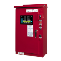
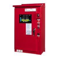
Diesel Plus Fire Pump Controllers
Fire Pump Controllers 1-1
Features
Typical Specifications
1. Approvals
A. The Fire Pump Controller shall meet Factory
Mutual Research (FM) 1321/1323.It shall be
listed by [Underwriters Laboratories (UL)],
[Canadian Standards Association (CSA)],
[New York Department of Buildings (NYSB)]
for fire pump service.
B. The controller shall be [12 volt / 24 volt] negative
ground, for use with Diesel Engine, Model manu-
factured by _______________.
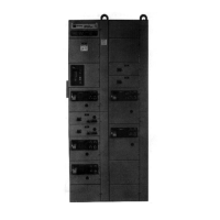
2. Construction
A. All internal components shall be front mounted
and wired for ease of inspection and mainte-
nance. All relays shall have visual indication to
show that the relays are energized. The control-
ler shall include an LCD display to indicate bat-
tery voltage and amperes as well as system
pressure, in PSI or Bars.
B. The controller shall have twin battery chargers
meeting Factory Mutual Research (FM) require-
ments. The battery chargers shall have reverse
polarity protection/ indication and be capable of
recharging a completely discharged battery with-
in 24 hours. The chargers shall auto detect the
input voltage of 100VAC to 240VAC and shall be
able to be programmed for either 12VDC or
24VDC output.
C. The controller shall come standard with a break-
er disconnect on the AC line and for both battery
connections.
3. Pressure Sensor
A. A solid-state 4-20mA pressure sensor shall be
provided. The pressure Start and Stop points
shall be adjustable in increments of one (1) PSI.
A low pressure pre-alarm, indicated with a flash-
ing green LED, shall denote a potential pump
starting condition and will remain lit once the
pump has started to indicate the starting cause.
4. Output Relays
A. Two (2) sets of alarm contacts (Form-C) rated
at 8A, 250VAC/30VDC, shall be provided for
remote indication of:
1. ENGINE RUN (10A)
2. LOW FUEL
3. AUTO MODE
4. COMMON ALARM
B. Two (2) ‘FUTURE’ relays, each containing two
sets of alarm contacts (Form-C) shall be provid-
ed. Relays can be factory set to indicate a spe-
cific alarm and shall be field programmable / ad-
justable to meet future site requirements:
C. The Common Alarm relay shall be energized
under normal conditions.
5. Enclosure
A. The controller shall be housed in a NEMA Type
2 (IEC IP11) drip-proof, powder baked finish,
freestanding enclosure.
B. Optional Enclosures:
1. NEMA 3R (IEC IP24) rain-tight enclosure.
2. NEMA 4 (IEC IP66) watertight enclosure.
3. NEMA 4X (IEC IP66) watertight 304 stain-
less steel enclosure.
4. NEMA 4X (IEC IP66) watertight 316 stain-
less steel enclosure.
5. NEMA 4X (IEC IP66) watertight corrosion re-
sistant enclosure.
6. NEMA 12 (IEC IP54) dust-tight enclosure.
6. Microprocessor Control
A. The following parameters shall be programma-
ble and included as standard:
1. START and STOP PSI points
2. High and Low Pressure Alarm Setpoints
3. STOP MODE: Manual or Auto
4. RUN PERIOD TIMER: 0-60 min
5. AC POWER FAILURE: Enable or Disable
6. SEQUENTIAL START TIMER: 0-300 sec.
7. WEEKLY TEST TIMER
8. PRESSURE DEVIATION: 1-99 PSI
9. LANGUAGE: English/French/Spanish/Other
B. The following visual and audible alarms shall be
provided:
FAIL TO START
LOW OIL PRESSURE
ENGINE OVERSPEED
BATTERY #1 FAILURE
BATTERY #2 FAILURE
REMOTE START
LOW PRESSURE
SPEED SWITCH FAULT
ECM SELECTOR IN ALT POSITION
FUEL INJECTOR MALFUNCTION
STARTER #1 FAILURE
STARTER #2 FAILURE
TRANSDUCER FAILURE
DATA CABLE DISCONNECT
DC FAIL
HIGH ENGINE TEMP.
ENGINE RUN
LOW FUEL
CHARGER #1 FAILURE
CHARGER #2 FAILURE
DELUGE VALVE
INTERLOCK ON
LOW SUCTION
ECM WARNING
ECM FAILURE
HIGH RAW WATER TEMPERATURE
LOW ENGINE TEMPERATURE
LOW RAW WATER FLOW
FUEL SPILL
For more information visit: www.chfire.com PS081002EN
 Loading...