14
Advanced Integration Connections
www.eaton.com/lightingsystems
†
Final dimmer output level is determined by the following combination:
●
High end trim level
●
Daylighting contribution
●
Demand Response value
If enough natural light is entering the space and any of these three features have been implemented, the target light level
may be lower than shown. Raise commands from pushbuttons or sliders do not override or raise the lighting above the
target threshold implemented by these advanced energy saving methods.
Room Controller Networking
This section applies to the RC3-PL-N, RC3D-PL-N and RC3DE-PL-N Room Controller models.
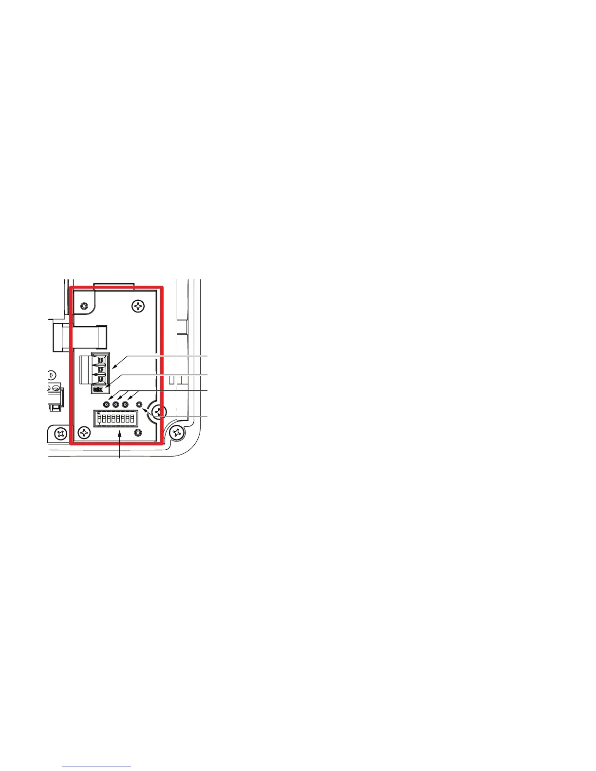
Room Controller Network Node
The diagram below calls out some of the various components of the network node.
RS-485 Connection
Address DIP Switch
Reset Button
Communication
Status LEDs
Terminating J
Network Wiring Notes
The Room Controller network is designed to communicate with other Room Controller and ControlKeeper network
panels using a lighting control RS-485 network for communications. This allows the panels to share information and to be
 Loading...


