16
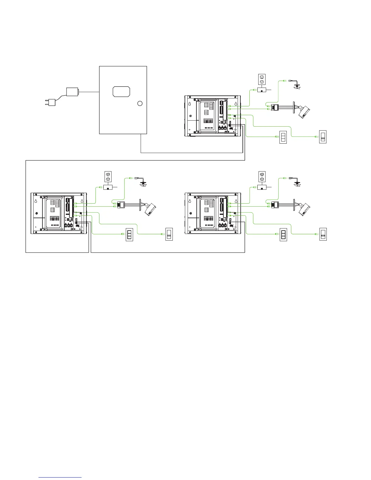
Advanced Integration Connections
www.eaton.com/lightingsystems
Room Controller Network Topology
1
2
3
4
5
6
Integration Controls Adjustable Skylights
Low EndHigh End
Energy
Options
Status Reset
0-10V Gain
Adjustment
Dimmer 3Dimmer 2Dimmer 1
+ --
++
-
0-10V Dimming
0-10V Dimming Outputs
-
+
Dimmer 3
Dimmer 2Dimmer 1
-
++
-
Blue - EM Line In
Blue - EM Loads Out
CAUTION: Bonding between conduit connections is not automatic and must be provided as part of the installation.
Black - Line In
White/Black - 120V N
White/Orange - 277V N
Blue - Load In
Yellow - Load 1 Out
Red - Load 2 Out
Purple - Load 3 Out
Energy Options DIP Switch
Demand Response Occupancy Not Used
1
2
34
Default 10%
20%
30%
40%
Occ
Vac (default)
Time
Clock
Alert
Mode
Demand
Response
A/V
Mode
+
-
Integration Controls
+
-
+
-
+
-
Green
Black
Red
White
Adjustable Skylights
Sensors
Receptacle
BMS/Out
Switchpack
QuickConnect Cables
Sensors
Slider
Station
Wallstations
Half Lights
Full Lights
All Off
Model: OCC-RJ45
Occupancy Sensor Coupler
Brown
Black
Red
Blue
120V Power
Receptacle Required
EIM
ControlKeeper
TouchScreen
The Ethernet Interface Module (EIM)
and Wireless Ethernet Interface
Module (WEIM) may be connected to
any Lighting Control Panel in the system
using the RS-232 cable included.
(Part #:52-018703-00)
QuickConnect Coupler
(GGRC-COUPLER)
Daylight sensor
(DSRC-FMOIR)
1
2
3
4
5
6
Integration Controls Adjustable Skylights
Low EndHigh End
Energy
Options
Status Reset
0-10V Gain
Adjustment
Dimmer 3
Dimmer 2Dimmer 1
+
- -
++-
0-10V Dimming
0-10V Dimming Outputs
-
+
Dimmer 3
Dimmer 2
Dimmer 1
-
+
+
-
Blue - EM Line In
Blue - EM Loads Out
CAUTION: Bonding between conduit connections is not automatic and must be provided as part of the installation.
Black - Line In
White/Black - 120V N
White/Orange - 277V N
Blue - Load In
Yellow - Load 1 Out
Red - Load 2 Out
Purple - Load 3 Out
Energy Options DIP Switch
Demand Response Occupancy Not Used
12
3
4
Default 10%
20%
30%
40%
Occ
Vac (default)
Time
Clock
Alert
Mode
Demand
Response
A/V
Mode
+
-
Integration Controls
+
-
+
-
+
-
Green
Black
Red
White
Adjustable Skylights
Sensors
Receptacle
BMS/Out
Switchpack
QuickConnect Cables
Sensors
Slider
Station
Wallstations
SPRC-R-20-120
20A Receptacle
Control
Half Lights
Full Lights
Wallstation
All Off
Slider Station
Occupancy/
Vacancy Sensor
(OAWC-DT-120W)
OCC-RJ45
(Occupancy Coupler)
QuickConnect Coupler
(GGRC-COUPLER)
Daylight sensor
(DSRC-FMOIR)
SPRC-R-20-120
20A Receptacle
Control
Wallstation
Slider Station
Occupancy/
Vacancy Sensor
(OAWC-DT-120W)
OCC-RJ45
(Occupancy Coupler)
QuickConnect Coupler
(GGRC-COUPLER)
Daylight sensor
(DSRC-FMOIR)
SPRC-R-20-120
20A Receptacle
Control
Wallstation
Slider Station
Occupancy/
Vacancy Sensor
(OAWC-DT-120W)
OCC-RJ45
(Occupancy Coupler)
Model: OCC-RJ45
Occupancy Sensor Coupler
Brown
Black
Red
Blue
1
2
3
4
5
6
Integration Controls Adjustable Skylights
Low EndHigh End
Energy
Options
Status Reset
0-10V Gain
Adjustment
Dimmer 3Dimmer 2Dimmer 1
+ -
-
++
-
0-10V Dimming
0-10V Dimming Outputs
-+
Dimmer 3
Dimmer 2
Dimmer 1
-
+
+
-
Blue - EM Line In
Blue - EM Loads Out
CAUTION: Bonding between conduit connections is not automatic and must be provided as part of the installation.
Black - Line In
White/Black - 120V N
White/Orange - 277V N
Blue - Load In
Yellow - Load 1 Out
Red - Load 2 Out
Purple - Load 3 Out
Energy Options DIP Switch
Demand Response Occupancy
Not Used
1
234
Default 10%
20%
30%
40%
Occ
Vac (default)
Time
Clock
Alert
Mode
Demand
Response
A/V
Mode
+
-
Integration Controls
+
-
+
-
+
-
Green
Black
Red
White
Adjustable Skylights
Sensors
Receptacle
BMS/Out
Switchpack
QuickConnect Cables
Sensors
Slider
Station
Wallstations
Half Lights
Full Lights
All Off
Model: OCC-RJ45
Occupancy Sensor Coupler
Brown
Black
Red
Blue
 Loading...


