18
Bringing the Room Controller Online
www.eaton.com/lightingsystems
Bringing the Room Controller Online
The Room Controller is pre-programmed and ready for operation out-of-the-box. If no adjustments are done, the unit will
operate from occupancy sensors, daylighting and wallstations.
To obtain maximum energy efficiency and occupant satisfaction, we recommend that you complete this short checklist to
verify the unit is operating optimally for the space being controlled.
Room Controller Verification Checklist
Room Location: ____________________
1.
Initial Power Up Response
Apply power to the Room Controller.
Verify that all lighting loads turn on to full for 3 seconds before beginning normal operation.
2. Verify Occupancy Sensor Operation
Verify that the occupancy sensor has been located properly to prevent false activation.
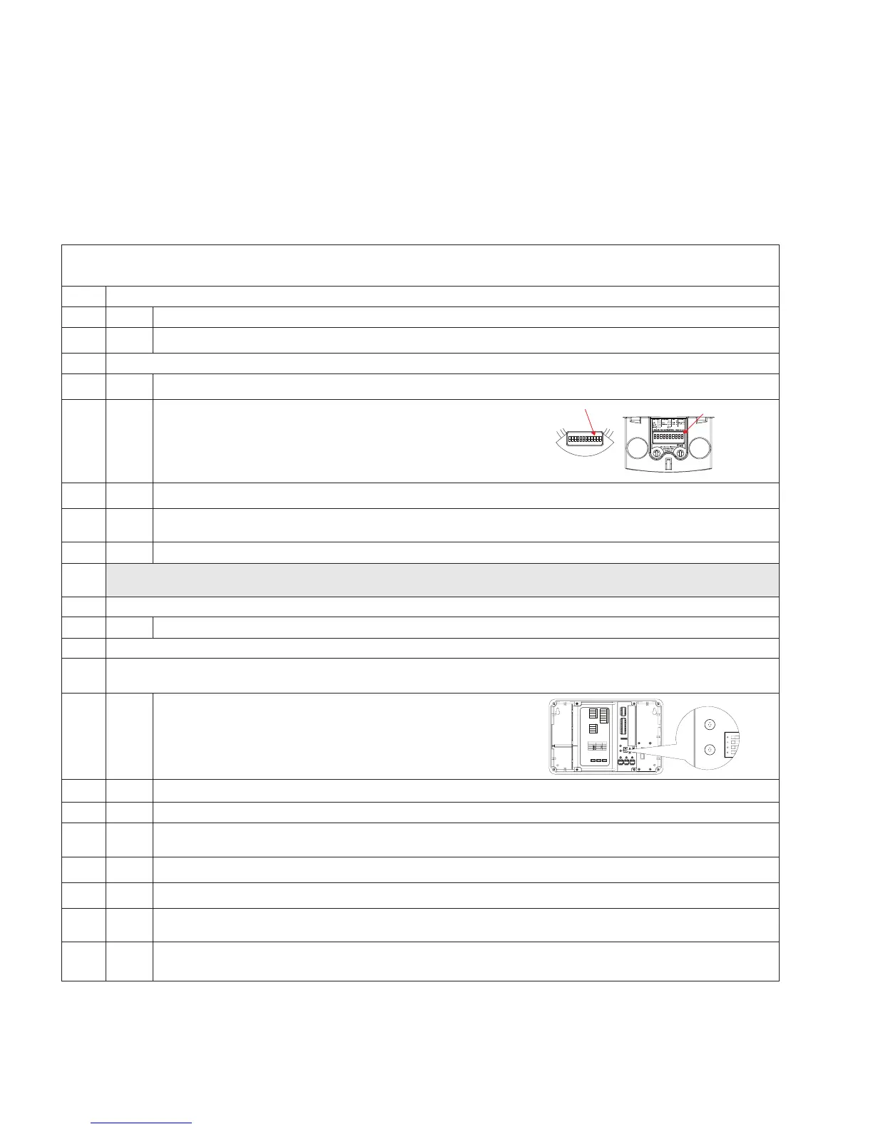
Wait 2 minutes from power-up, then place OAC or OAWC sensors in Test Mode by
moving DIP Switch 10 out of its current position, wait 3 seconds, then put back into
its original position.
12345678 910
Move around the controlled area, verifying that the ocupancy sensor LEDs flash with each motion and stop flashing when you stand still.
If not already ON, turn lighting ON from the wallstation controls. For any stations with Quiet Time buttons, make sure that Quiet Time
Mode is de-activated (LED is not lit).
Leave the room and wait approximately one minute for the lighting to turn OFF.
If lighting does not turn OFF, refer to “Room Controller Troubleshooting” on page 23. Sensors will automatically exit Test Mode after a period of 5
to 10 minutes (timing is dependent on sensor model) and begin automatically adjusting based on occupancy patterns.
3. Verify Wallstation Operation
Check each wallstation for proper operation of intended loads.
4. Set Minimum and Maximum Trim levels
Trim levels have been preset to approximately 90% maximum. Additional energy savings can be gained by adjusting the trim further if electric
lighting contribution is over the target illuminance for the space.
Locate the position of the trim level adjustment dials on the Room Controller.
Low End High End
Energy
Options
Statu
eset
0-10V Gain
Adjustment
Dimmer 3 Dimmer 2 Dimmer 1
+
--
++
-
0-10V Dimming
Integration Controls Adjustable Skylights
0-10V Dimming Outputs
-
+
Dimmer 3 Dimmer 2 Dimmer 1
-
++
-
Blue - EM Line In
Blue - EM Loads Out
CAUTION: Bonding between conduit connections is not automatic and must be provided as part of the installation.
Black - Line In
White/Black - 120V N
White/Orange - 277V N
Blue - Load In
Yellow - Load 1 Out
Red - Load 2 Out
Purple - Load 3 Out
Energy Options DIP Switch
Demand Response
Occupancy
Not Used
12 34
Default 10%
20%
30%
40%
Occ
Vac (default)
Time
Clock
Alert
Mode
Demand
Response
A/V
Mode
+
-
Integration Controls
+
-
+
-
+
-
Green
Black
Red
White
Adjustable Skylights
Sensors
Receptacle
BMS/Out
Switchpack
QuickConnect Cables
Sensors
Slider
Station
Wallstations
Trim levels are being adjusted at night or shades have been used to darken the space during daylight hours.
Using the wallstations, turn ON all controlled lighting. For fluorescent lighting loads, wait one minute to allow lamps to warm up.
Using a small screwdriver, twist the maximum trim dial counter clockwise, then fully clockwise again. The lights will go full bright and the
Room Controller will enter Adjustment Mode.
Turn the maximum trim adjustment dial counter-clockwise in small increments until the light level is at the desired maximum level.
Turn the minimum trim dial clockwise then fully counter clockwise. The light level in the room will go full dim.
Turn the minimum trim dial clockwise in small increments until you begin to notice the light level increasing in the monitored space, then
turn the dial slightly counter clockwise from where this change begins.
Save the new trim settings and go back to normal operation by pressing the “All OFF” button on any wallstation.
If “All OFF” is not pressed, the controller will automatically save these settings after two minutes.
 Loading...