2
3
4
5
7
6
6
8
6
7
Figure 18. Installing hinge and bracket assemblies
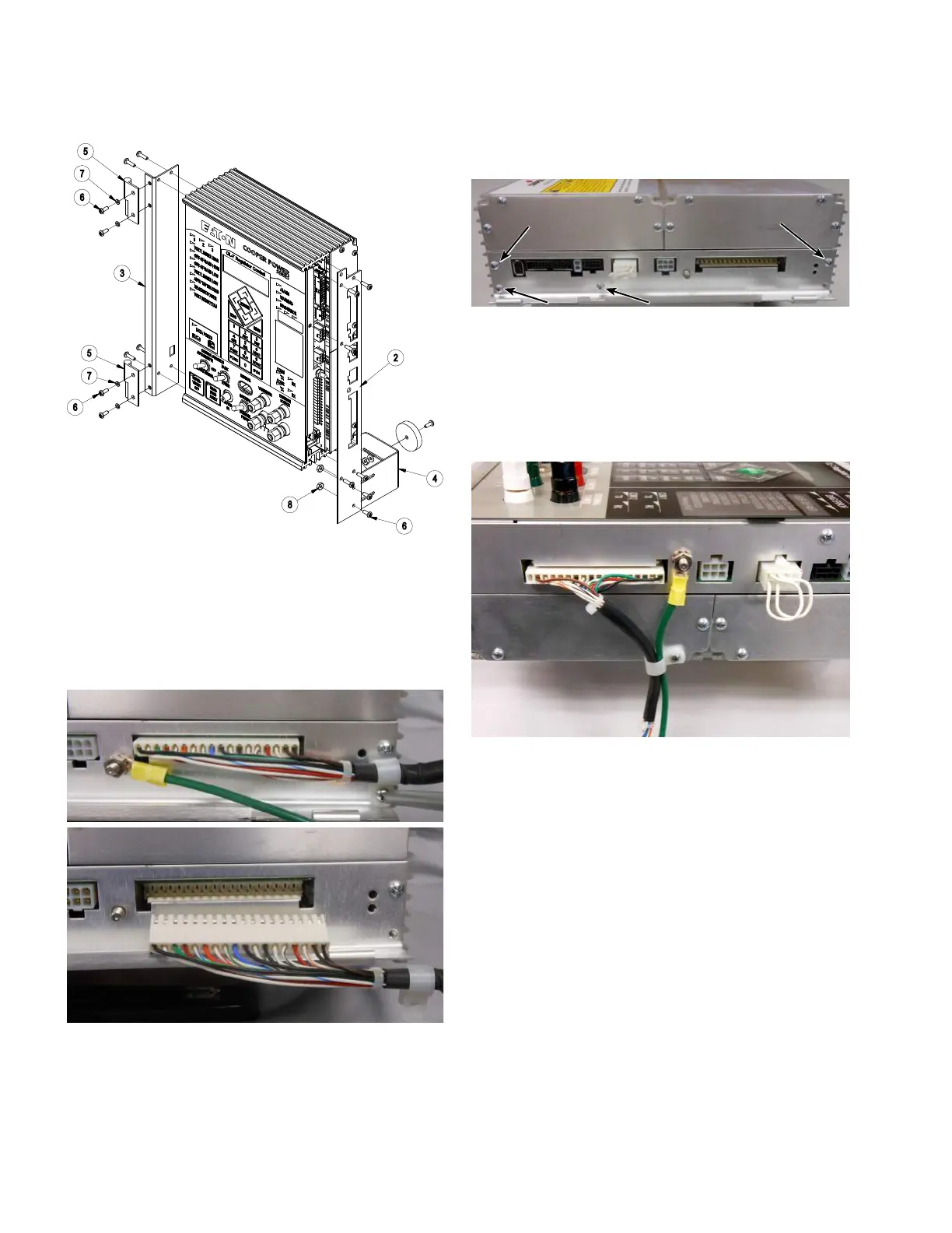
5. Remove the strain relief screw (retain the screw and
strain relief device) and disconnect the white connector
from the side of the CL-7 control panel. See Figure 19.
6. Using a 3/8-inch wrench, remove the green ground
wire from the side of the panel; retain the washer and
nut. See Figure 19.
Figure 19. Removal of existing ground wire and wiring
harness
7. Remove the remaining four screws holding on the
hinged side panel; retain the screws. See Figure 20.
Figure 20. Removal of hinged side panel from CL-7
control
8. Install the right face place to the side of the control
using the screws retained from Step 5 and the last
step. See Figure 18.
9. Install the Siemens Corporation wiring harness
(Item1). See Figure 21.
Figure 21. Installing ground wire and Siemens
Corporation wiring harness
10. Install the extended green ground wire (Item9)
using the washer and nut retained from Step 6. See
Figure 21.
11. Route the wiring harness and ground wire through
the strain relief device and secure using the screw
and strain relief device retained in Step 5 as shown in
Figure 21.
8
CL-7 Control Panel Retrofit
InstallatIon InstructIons MN225018EN April 2018

 Loading...


