12. Install the adhesive cable tie anchors (Item10) as
shown in Figure 22 and secure the wiring harness and
ground wire using the provided cable ties (Item11).
Trim back the cable ties as necessary.
Figure 22. Installing ground wire and harness cable ties
13. Install the Siemens Corporation retrofit kit magnet
assembly (Item4) as shown in Figure 18 using the
provided hardware (Items6 and 8).
14. Slide the CL-7 control panel onto the existing hinge
pins.
15. Connect the green ground wire to the enclosure
ground. The best spot to make the ground connection
usually is under the screws holding the enclosure
terminal block into the control cabinet. See Figure 24.
16. Using a screwdriver, adjust the magnet depth of the
magnet bracket as needed so that the CL-7 control
panel remains in a closed position.
1 7. Install the terminal connector (Figure 23) into the
existing enclosure terminal block (Figure 24), securing
with the wing-nuts retained from Step 1.
Figure 23. Siemens Corporation-style terminal
connector
Figure 24. Siemens Corporation enclosure terminal
block
18. Review the Siemens Corporation nameplate to
determine correct overall Potential Transformer (PT)
ratio entered at FC 44 on control. Divide the Load Volts
shown by the corresponding Control Volts to obtain the
Overall PT Ratio.
19. If a source-side PT will be used, on the terminal
connector (Figure 25), move the white/brown wire
from terminal P2 and place it on terminal U2. If this
is not done, the control will use a calculation to
determine the source-side voltage. If utilizing a source-
side PT, make sure to enter the Internal PT Ratio into
the control at FC 44. The Internal PT Ratio can be
determined by dividing the Source Volts shown on the
nameplate for reverse power flow by the corresponding
Control Volts. Also, when using a source-side PT, the
Vin PT Configuration (FC 146) must be set for Vin
Mode.
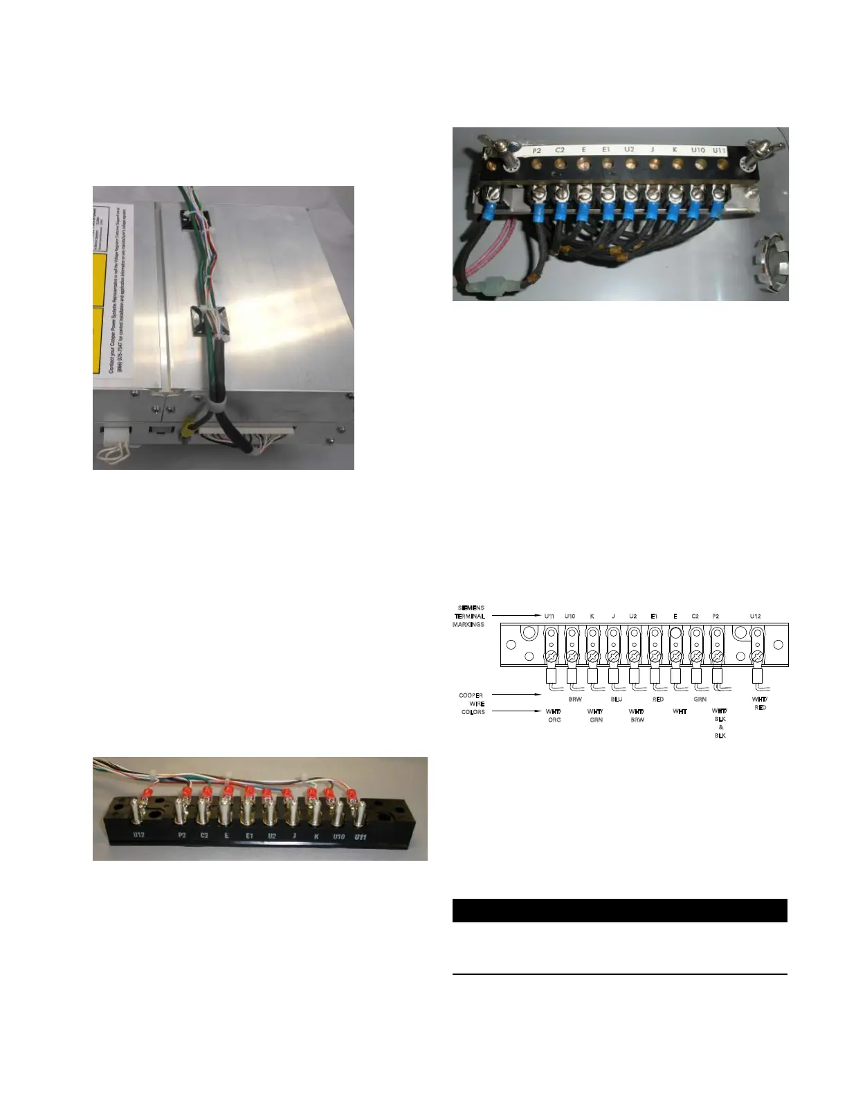
U 11 U10 K J U2 E1 E C2 P2 U12
TERMINAL
MARKINGS
COOPER
WIRE
COLORS
WHT/
ORG
BRW
WHT/
GRN
BLU
WHT/
BRW
RED
WHT
GRN
WHT/
BLK
&
BLK
WHT/
RED
Figure 25. Siemens Corporation terminal connector
with markings and wire colors—wired for use with
source-side PT
20. Complete the control programming and testing as
required. Refer to document MN225003EN, CL-7
Control Installation, Operation, and Maintenance
Instructions for proper control configuration and start
up procedures.
IMPORTANT
If the neutral light does not illuminate when the regulator
is in neutral, try flipping the neutral light switch to the
opposite position. See Figure 14.
9
CL-7 Control Panel Retrofit
InstallatIon InstructIons MN225018EN April 2018

 Loading...


