3
2
4
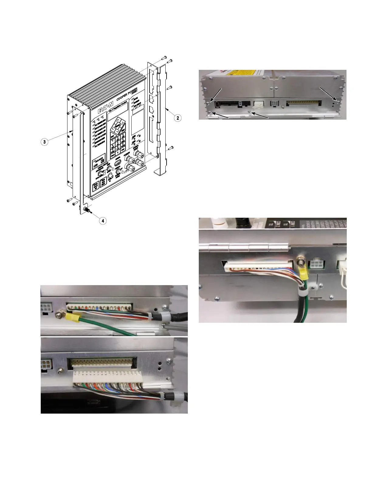
Figure 28. Installing hinge and bracket assemblies
4. Remove the strain relief screw (retain the screw and
strain relief device) and disconnect the white connector
from the side of the CL-7 control panel. See Figure 29.
5. Using a 3/8-inch wrench, remove the green ground wire
from the side of the panel; retain the wire, washer, and
nut. See Figure 29.
Figure 29. Removal of existing ground wire and wiring
harness
6. Remove the remaining four screws holding on the
hinged side panel; retain the screws. See Figure 30.
Figure 30. Removal of hinged side panel from CL-7
control
7. Install the General Electric hinge bracket on the right
side of the control using the screws retained from
Step 4 and the last step. See Figure 28.
8. Install the General Electric fork-style wiring harness
(Item1). See Figure 31.
9. Reinstall the green ground wire using the washer and
nut retained from Step 6. See Figure 31.
10. Route the wiring harness through the strain relief
device retained from Step 5 and secure under a screw
as shown in Figure 31.
Figure 31. Installing ground wire and General Electric
fork-style wiring harness
11. Install the CL-7 control panel into the control box by
mounting it onto the existing hinges using the hinge
pins retained from Step 1.
12. Connect the green ground wire to the enclosure
ground.
13. Install the fork-terminal connectors into the existing NN
terminal blocks (Figure 32 and Table 5).
11
CL-7 Control Panel Retrofit
InstallatIon InstructIons MN225018EN April 2018

 Loading...


