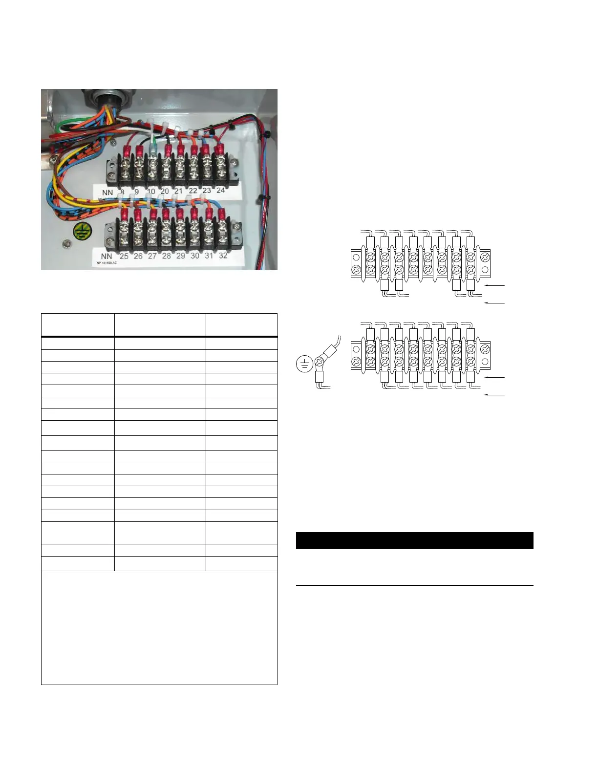
Figure 32. General Electric terminal board NN
Table 5. Terminal block NN identification
General Electric
Labels
1
Eaton Wiring Harness Required Signals
32 — Source PT
31 White/Red Neutral Light
30 Brown Operations Counter
29 White/Orange Drag hand reset
28 White/Green Lower
27 Blue Raise
26 White, White Common
25 — —
Cabinet Ground
2
Red, Red CT Ground
24 Red, White CT Ground
23 Green CT
22
3
— —
21
3
— —
20
3
— —
10 White, White Common
9 Black, White/Black,
White/Brown
4
Load PT
8 — —
Cabinet Ground
2
White Common
1 General Electric terminal labels and wiring has changed over time.
Consult the regulator documentation for terminal markings and required
signals when connecting the wiring harness.
2 Connect to any convenient ground stud.
3 Some General Electric units will have a jumper between terminals 8
or 9 and terminals 20, 21, or 22. If this is the case, leave the jumper
in place. Terminals 20, 21, and 22 are used for PT tap adjustments.
A system voltage change may require a change in the position of the
jumper. See the nameplate for the correct jumper position.
4 The white/brown wire will be moved to terminal 32 if a source PT is
present and is to be used.
14. Close and secure the CL-7 control panel using the self-
adjusting latch.
15. Review the General Electric nameplate to determine
correct overall Potential Transformer (PT) ratio entered
at FC 44 on control.
16. If a source-side PT will be used, move the white/
brown wire from terminal 9 and place it on terminal 32
as shown in Figure 33. If this is not done, the control
will use a calculation to determine the source-side
voltage. If utilizing a source-side PT, make sure to enter
the Internal PT Ratio into the control at FC44. Also,
when using a source-side PT, the Vin PT Configuration
(FC146) must be set for Vin Mode.
25
COOPER
WIRE
COLORS
26 27 28 29 30 3231
8 9 10 20 21 22 2423
NN
NN
WHT
&
WHT
BLU
WHT/
GRN
WHT/
ORG
BRW
WHT/
RED
WHT/
BRW
BLK
&
WHT/
BLK
WHT GRN RED
&
WHT
GE
TERMINAL
COOPER
WIRE
COLORS
GE
TERMINAL
RED
&
RED
WHT
Figure 33. Connections to General Electric terminal
board –wired for use with source-side PT
1 7. Complete the control programming and testing as
required. Refer to document MN225003EN, CL-7
Control Installation, Operation, and Maintenance
Instructions for proper control configuration and start up
procedures.
IMPORTANT
If the neutral light does not illuminate when the regulator
is in neutral, try flipping the neutral light switch to the
opposite position. See Figure 14.
12
CL-7 Control Panel Retrofit
InstallatIon InstructIons MN225018EN April 2018

 Loading...


