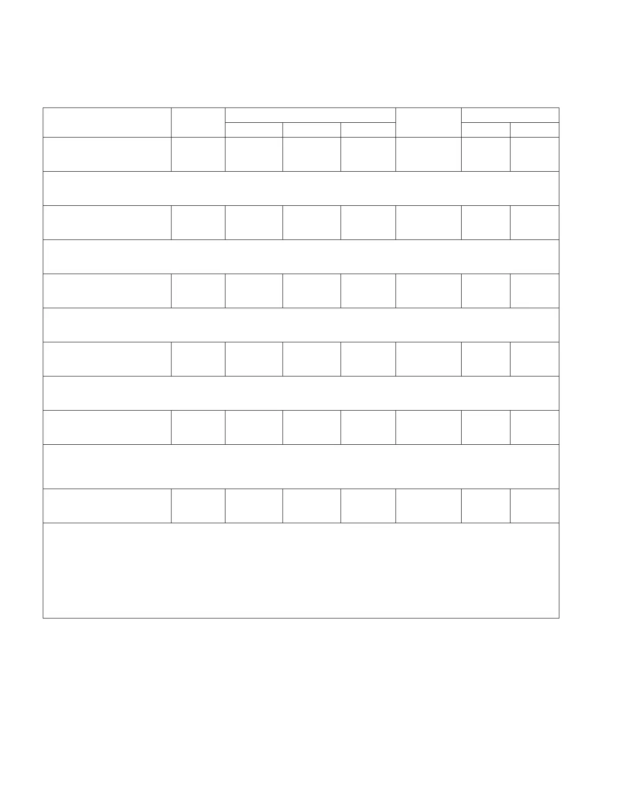
Table10. Function codes (continued)
Parameter
Unit of
Measure
Security Level
Default Value
Key Entry Limit
To Read To Write To Reset Low High
045 Adaptive ADD-AMP
5% Limit
XXX %
% View Modify NA 100 100 160
•Adaptive ADD-AMP setting found in the Limit Switch Settings chart on the nameplate at the
5% Level.
•SOFT-ADD-AMP (FC 70) must be set to Adaptive to activate this feature.
045 Adaptive ADD-AMP
6 1/4% Limit
XXX %
% View Modify NA 100 100 160
•Adaptive ADD-AMP setting found in the Limit Switch Settings chart on the nameplate at the
6 1/4% Level.
•SOFT-ADD-AMP (FC 79) must be set to Adaptive to activate this feature.
045 Adaptive ADD-AMP
7 1/2% Limit
XXX %
% View Modify NA 100 100 160
•Adaptive ADD-AMP setting found in the Limit Switch Settings chart on the nameplate at the
7 1/2% Level.
•SOFT-ADD-AMP (FC 79) must be set to Adaptive to activate this feature.
045 Adaptive ADD-AMP
8 3/4% Limit
XXX %
% View Modify NA 100 100 160
•Adaptive ADD-AMP setting found in the Limit Switch Settings chart on the nameplate at the
8 3/4% Level.
•SOFT-ADD-AMP (FC 79) must be set to Adaptive to activate this feature.
046 Demand Time
Interval
XX.X Minutes
Minutes View Modify NA 15.0 0.1 60.0
•This is the time period during which the demand integral is performed for all demand
metering readings.
•Demand readings represent the values which produce actual heating effects in electrical
equipment and do not respond to the continuous fluctuations which occur on the line.
047 Voltage
Calibration
XXX.X Volts
Volts View Admin NA See Note 110.0 130.0
•The voltage which the control actually measures is displayed at FC 47. In the example
given in FC 44 description, FC 47 would indicate 125.1 V when FC 6 indicated 120 V.
•To calibrate, this value is compared to a reference voltmeter and if different, is changed
to display the correct value.
•Note: A default calibration factor is programmed into non-volatile memory at the factory;
adjustments should not be necessary in the field.
•See Section 8: Troubleshooting: Control calibration.
•In addition to the low and high limits, the user must enter a value that is within 5% of
the displayed value.
62
INSTALLATION, OPERATION, AND MAINTENANCE INSTRUCTIONS MN225003EN April 2018
CL-7 Voltage Regulator Control

 Loading...


