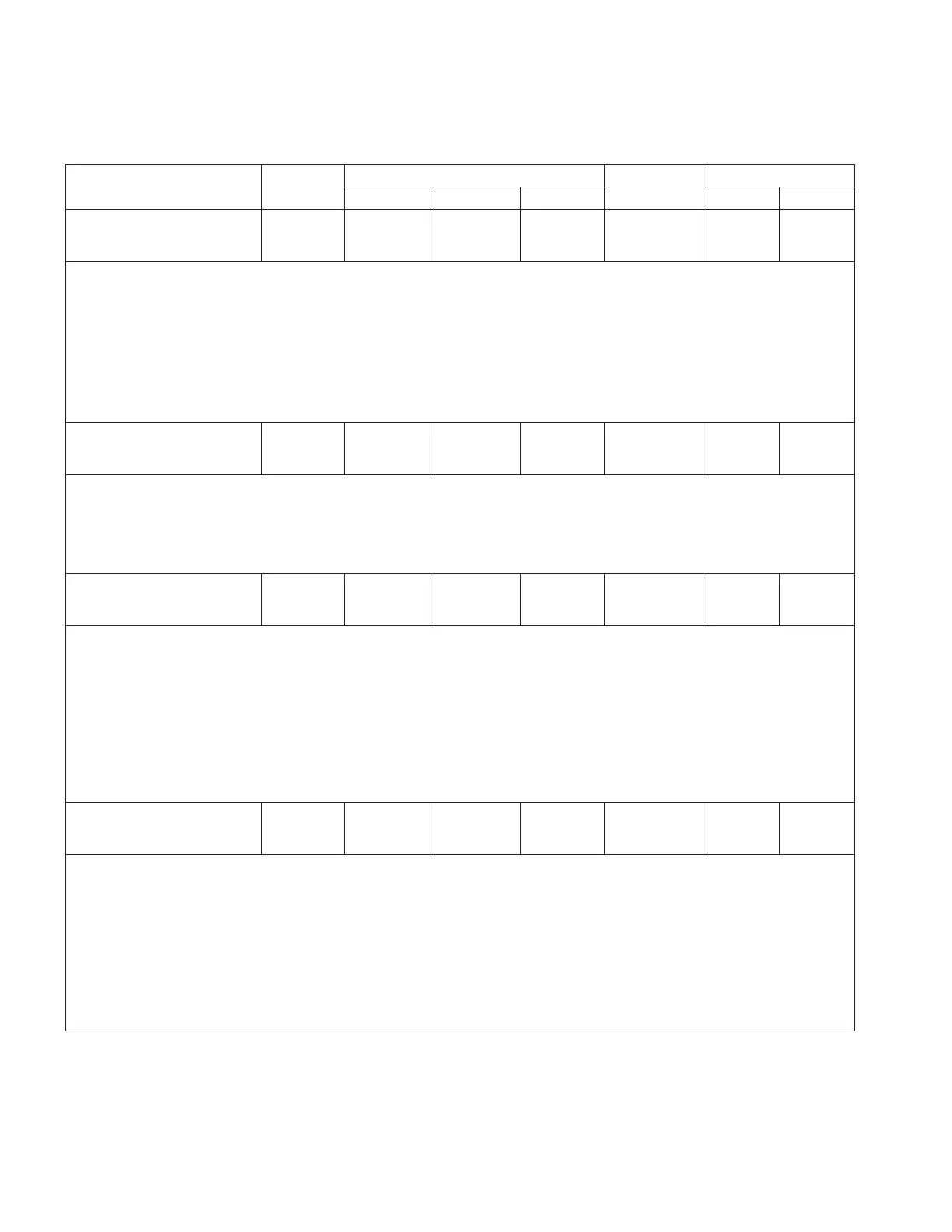
Table10. Function codes (continued)
Parameter
Unit of
Measure
Security Level
Default Value
Key Entry Limit
To Read To Write To Reset Low High
052 Reverse
Bandwidth
X.X Volts
Volts/% View Modify NA 2.0 1.0 6.0
•The bandwidth is defined as that total voltage range, around the set voltage, which the
control will consider as a satisfied (in-band) condition during reverse power flow.
•Example: A bandwidth of 3.0 V and a set voltage of 120.0 V will establish a low limit of
118.5 V and a high limit of 121.5 V.
•See FC 2 and Section 6: Control Features: Reverse power operation.
•If an alternate configuration is active, the fourth LCD line displays which one is active,
e.g. (ALT CONFIG 1).
•If FC 148 Nominal Load Voltage is set to 240 Volts, limits are expanded (doubled).
•If FC 148 is set to System Line Voltage, this setting must be set as a percentage of the
set voltage.
053 Reverse
Time Delay
XXX Seconds
Seconds View Modify NA 45 5 180
•The time delay is the period of time (in seconds) that the control waits, from the time
when the voltage first goes out-of-band to the time when a tap change is initiated during
reverse power flow.
•See FC 3 and Section 6: Control Features: Reverse power operation.
•If an alternate configuration is active, the fourth LCD line displays which one is active,
e.g. (ALT CONFIG 1).
054 Rev Line Drop
Comp. Resistance
XX.X Volts
Volts/% View Modify NA 0.0 -96.0 96.0
•The resistive line-drop compensation value is used to model the resistive line voltage
drop between the regulator and the center of regulation.
•The control uses this parameter, in conjunction with the regular configuration (FC 41) and
the load current, to calculate and regulate to the compensated voltage (displayed at FC
8) during the reverse power flow.
•See FC 4 and Section 6: Control Features: Reverse power operation.
•If an alternate configuration is active, the fourth LCD line displays which one is active,
e.g. (ALT CONFIG 1).
•If FC 148 Nominal Load Voltage is set to 240 Volts, limits are expanded (doubled).
•If FC 148 is set to System Line Voltage, this setting must be set as a percentage of the
set voltage.
055 Rev Line Drop
Comp. Reactance
XX.X Volts
Volts/% View Modify NA 0.0 -96.0 96.0
•The reactive line-drop compensation value is used to model the reactive line drop voltage
between the regulator and the center of regulation.
•The control uses this parameter, in conjunction with the regulator configuration (FC 41)
and the load current, to calculate and regulate to the compensated voltage (displayed at
FC 8) during the reverse power flow.
•See FC 5 and Section 6: Control Features: Reverse power operation.
•If an alternate configuration is active, the fourth LCD line displays which one is active,
e.g. (ALT CONFIG 1).
•If FC 148 Nominal Load Voltage is set to 240 Volts, limits are expanded (doubled).
•If FC 148 is set to System Line Voltage, this setting must be set as a percentage of the
set voltage.
64
INSTALLATION, OPERATION, AND MAINTENANCE INSTRUCTIONS MN225003EN April 2018
CL-7 Voltage Regulator Control

 Loading...


