i-on40 Before You Begin
Page 5
5. 20VAC input (from transformer).
6. Battery connector.
7. Kick Start pins.
8. Ethernet socket.
9. “Heartbeat” LED
10. RS485 terminator.
11. Reset Codes pins.
12. Plug by output connector pins 13-16.
13. Plug by output connector pins 1 to 12.
14. Plug on Comms activity LED.
15. Sockets for plug on module.
Figure
Control Unit Printed Circuit Board
1. Aux power.
2. Outputs (relay).
3. Aux power.
4. Keypad bus.
5. Wired zone connectors.
6. Ethernet connector.
7. Loudspeaker.
8. Wired siren tamper return.
9. Outputs (transistorised).
10. 14.4V Siren supply (not used in UK).
Figure
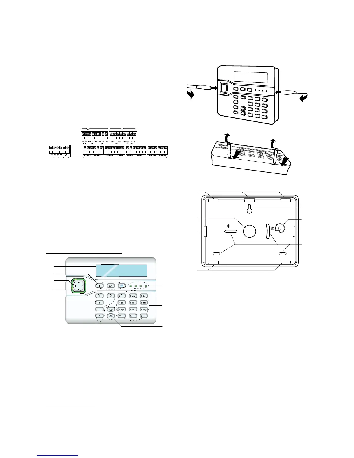
Control Unit Main Connectors
i-KP01 Controls and Displays
1. LCD display (2 x 20 characters).
2. Programming keys.
3. Navigation keys
4. Alert LEDs
5. Setting and unsetting keys.
6. Panic Alarm (PA) keys.
7. Number/text keys.
8. Set/Unset LEDs.
Figure
Controls and Displays
Opening the i-kp01
Note: For EN50131-3:2009, 8.7 the keypad is a
type B ACE, fixed.
To open the keypad first gently prise off the trim
on the front and remove the two screws. Next,
carefully lever the front of the keypad (containing
the pcb and display) away from the keypad rear
housing.
Figure
Opening the Keypad
1. Central keyhole.
2. Rear tamper shroud.
3. Cable entry.
4. Fixing holes.
Figure

 Loading...


