2
IZM20/IZM32 Shutters
IZM-SH203/IZM-SH204
and IZM-SH323/IZM-SH324
EATON CORPORATION www.moeller.net/en/support
08/10 AWA1230-2579
Effective August 2010
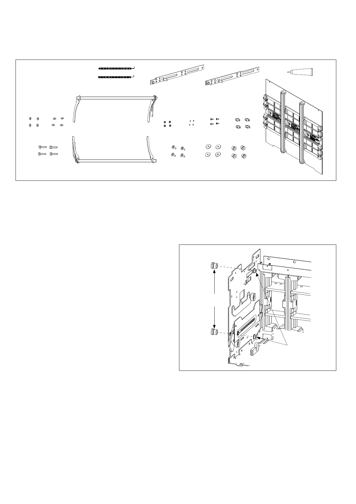
Figure 2. Contents of Kit
(A)
(B)
(C)
(D)
(G)
(H)
(P)
(Q)
(N)
(L)
(K)
(I)
(J)
(M)
(O)
(E)
(F)
Kit parts identification
Refer to Figure 2 for visual identification of the parts listed below:
(A) M6 hex nut (four)
(B) M6 x 30 screw (eight for six-pole, ten for eight-pole)
(C) M6 lock washer (four)
(D) Shutter spring (two)
(E) Upper shaft assembly (two)
(F) Lower shaft assembly (two)
(G) Top link slide assembly (one)
(H) Bottom link slide assembly (one)
(I) M4 nut with lock washer (four)
(J) Link mounting screw (four)
(K) O-ring (four)
(L) M4 x 10 screw (four)
(M) M6 x 25 wide washer (four)
(N) M12 E-clip (four)
(O) Shaft collar (four)
(P) Lubricant (one)
(Q) Shutter panel assembly (two)
(R) Bottom bearing—double wide shaft (one)
(S) Shaft joint (two)
(T) M8 x 8 hex bolt (four)
(U) M8 serrated lock washer (four)
(V) Top bearing—double wide shaft (one)
(W) M6 serrated lock washer (three)
(X) M6 x 12 thread-forming screw (three)
(Y) Barrier panel (one)
Section 2: Installation of cassette
shutter kit
Proceed with the following seven steps.
Step 1: Install two shaft collars (O) on left-side sheet (on right-side
sheet for right-side mounting). Fasten the grooves on the collars
with M12 E-clips (N).
Figure 3. Step 1
Shaft
Collar (O)
M12
E-Clip (N)

 Loading...