17
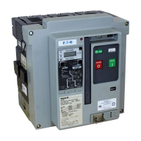
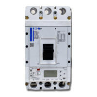
Overview of the Magnum PXR low voltage circuit breaker
MAGNUM PXR PRODUCT GUIDE PA013006EN September 2022 www.eaton.com
1
Table 1. Terminal to accessory assignment
PXR point
position
PXR point
name
General description Function Individual point description
C1 O1NO
Overcurrent trip switch 1 Indicates when breaker opens via the trip unit
Overcurrent trip switch 1 make
C2 O1C Overcurrent trip switch 1 common
C3 O1NC Overcurrent trip switch 1 break
C4 O2NO
Overcurrent trip switch 2 Indicates when breaker opens via the trip unit
Overcurrent trip switch 2 make
C5 O2C Overcurrent trip switch 2 common
C6 O2NC Overcurrent trip switch 2 break
C7 G1
External ground fault source / zero
sequence sensor
External ground fault sensor trip unit input for source /
zero sequence sensing
Ground fault sensor lead 1
C8 G2 Ground fault sensor lead 2
C9 SC Closing spring charged Closed when spring is fully charged Spring charged switch output
C10 RY1
Trip unit relays
Alarm 1 - Default setting: Maintenance mode active
(ARMS trip units) or Health warning (non-ARMS trip
units)
Configurable relay 1
C11 RY2
Alarm 2 - Default setting: Ground fault trip (LSIG trip
units) or High load alarm (LSI trip units)
Configurable relay 2
C12 RY3 Alarm 3 - Default setting: Any current protection trip Configurable relay 3
C13 RYC Relay common Configurable relay common
C14 +24V Trip unit auxiliary power supply input External trip unit power Auxilliary power supply positive
C15 0V Auxilliary power supply common
C16 N
External neutral current sensor
Connect to the external neutral current sensor, jumper if
not needed and in a 4-pole breaker
Neutral current sensor lead 2
C17 N• Neutral current sensor lead 1 (N DOT)
C18 MM Remote maintenance mode enable Enable maintenance mode via a remote switch Maintenance mode signal
C19 ZI ZSI - Input
Connect to other ZSI enabled breakers in the system
(maximum length of 25 meters (75 feet) using AWG #22
wire)
Zone selective interlock input
C20 ZC Trip Unit Circuit Common Zone selective interlock common
C21 ZO ZSI - Output Zone selective interlock output
C22 MBA
Modbus RTU Modbus RTU communication onboard trip unit
Non-Inverting (+) Signal
C23 MBB Inverting (-) Signal
C24 MBG RS485 ground
C25 a COMO Future
C26 a COMC Future
C27 a CM3
Trip unit communication adapter
module (CAM) connections
Connect to a CAM
RX+ / CMM1
C28 a CM4 RX- / CMM2
C29 a CM1 TX+ / CMM3
C30 a CM2 TX- / CMM4
C31 a Future
C32 a Future
C33 a Future
C34 a Future
C35 a Future
C36 a Future
 Loading...

