37
PXR trip unit and communication modules
MAGNUM PXR PRODUCT GUIDE PA013006EN September 2022 www.eaton.com
3
Arcflash reduction maintenance system
The Arcflash Reduction Maintenance System/Maintenance
Mode function of the PXR trip units can reduce arc flash
incident energy that is generated on a fault condition.
This is accomplished by a separate trip circuit that, when
armed, provides a fast-acting response to the fault. This
is separate from the normal system protection setting of
instantaneous. The PXR ARMS protection operates at the
same time as the normal LSIG protection but provides a
faster immediate trip over the setting level. For most fault
conditions as shown in the time current curve below the
ARMS protection will override the protection, the normal
LSIG protection provides an added backup function.
Eaton’s Arcflash Reduction Maintenance System employs
a separate, dedicated trip circuit that results in clearing
times that are faster than standard instantaneous tripping.
This provides superior arc flash reduction to competitors’
systems that simply lower the standard instantaneous
pickup set point or employ ZSI tripping.
There are three ways to arm the Arcflash Reduction
Maintenance System/Maintenance Mode setting. One
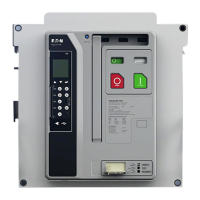
method is locally at the trip unit front panel. Both the PXR
20 and the PXR 25 have a two-position switch on the front
of the trip unit for Maintenance Mode. Turning the switch
to the ON position will locally arm the function. The setting
for the level of reduction can be set in the trip unit menus
or by using PXPM.
For the second method of arming the Maintenance Mode
function, a remote switch or external relay contact wired
through the breaker secondary terminals can remotely arm
the Maintenance Mode protection function. A high-quality
gold-plated or palladium contact on the switch or relay is
required for this method. See Figure 34 for wiring.
A third method to arm the Maintenance Mode setting
is via a communication device, such as a Modbus RTU
controller. An Eaton Dashboard display interface module
can be used as one of the communication methods to arm
the protection function remotely from a safe distance.
The Arcflash Reduction Maintenance System setting has
six unique settings (1.5, 2.5, 4.0, 6.0, 8.0, 10.0 x I
n
) for the
pickup of the reduction setting (shown in Figure 38) is the
ARMS 1.5x active protection curve. This setting level can
be used to prevent inrush currents or load surges from
triggering the ARMS function. The new PXR trip units are
now able to go to a new lower setting of 1.5x the frame
rating I
n
for the maximum reduction of arc flash energy.
For all three arming methods, the PXR trip units provide a
local indication as a blue LED ring around the trip unit ON/
OFF switch to confirm the Maintenance Mode function
is on or off. The trip unit display will show a confirmation
screen that verifies the arming. In addition, one of the
three programmable relays in the frame module of the trip
unit can be set to indicate the status of the maintenance
mode protection. For breakers ordered with an ARMS trip
unit, relay 1 comes programmed for Maintenance Mode
Active from the factory. This normally open relay contact
allows the user to wire in an external stack light or annun-
ciator for remote indication.
The Maintenance Mode function will provide fast tripping
even when the regular Instantaneous is set to OFF. The
instantaneous LED position is also used to indicate a
trip initiated by the Maintenance Mode setting. The LCD
display, if powered, will indicate that a Maintenance Mode
trip occurred, and the unit’s trip buffer will log the event.
Figure 38. ARMS 1.5x active protection curve
Figure 37. Maintenance mode switch
 Loading...

