Do you have a question about the Eaton Magnum PXR and is the answer not in the manual?
| Brand | Eaton |
|---|---|
| Model | Magnum PXR |
| Category | Circuit breakers |
| Language | English |
States the primary intent of the instructional booklet for installation, operation, and maintenance.
Emphasizes the strict observance of all safety codes, standards, and regulations.
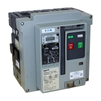
Describes Magnum PXR and PD-SB circuit breakers, frame sizes, ratings, and standards.
Highlights built-in interlocks and safety features for personnel and proper operation.
Outlines essential safety practices for personnel involved in installation, operation, and maintenance.
Defines qualifications for personnel operating and maintaining low voltage power circuit breakers.
Lists additional resources and documentation available for Magnum PXR and PD-SB circuit breakers.
Covers receiving and handling of circuit breakers supplied with assemblies or as separate components.
Lists essential tools recommended for the proper installation and maintenance of circuit breakers.
Provides instructions and precautions for safely unpacking new circuit breakers to prevent damage.
Details safe procedures and precautions for lifting circuit breakers using appropriate equipment.
Gives guidance on storing circuit breakers in their original containers in a clean, dry environment.
Advises visual inspection for damage and checking the current rating label on the trip unit frame.
Describes how to install drawout circuit breakers onto extension rails in structures.
Explains how rejection interlocks prevent incompatible breaker/cassette combinations.
Details the four normal positions for drawout circuit breakers: REMOVE, DISCONNECT, TEST, and CONNECT.
Provides instructions on how to lever the circuit breaker into and out of its compartment.
Describes the differences of fixed breakers from drawout types, including lack of levering device.
Introduces common features of drawout and fixed mounting configurations for circuit breakers.
Advises operating circuit breakers manually and/or electrically before putting them into service.
Describes the rigid frame housing construction using engineered thermoset composite resins.
Explains the individually enclosed current-carrying pole units with primary contact assemblies.
Details the composition of primary moving contact assemblies and their fingers.
Describes the primary stationary contact as a combination of a conductive pad and an arc runner.
Explains the proven cam and spring design of the operating mechanism and its access.
Details manual charging of closing springs and operation via manual OPEN/CLOSE buttons.
Mentions optional devices for automatic closing or tripping and their availability.
Describes how springs are charged using an electrical operator or manually.
Explains the mechanical and electrical anti-pump features preventing repeated closing on faults.
Describes arc chambers used for insulating poles and the arc chute mounting.
Introduces the Power Xpert Release (PXR) trip unit and its components.
Details the PXR trip unit's flexibility, features, and configuration options for protection.
Describes the trip unit's function, replacement, and self-powered nature.
Explains the permanently mounted frame module holding rating, sensor calibration, and interface circuits.
Describes the voltage module converting line voltage for trip unit sensing, included on PXR 25.
Details integrated test functions requiring no separate kit, using on-board circuits and PXPM software.
Explains permanently installed internal current sensors and their function in powering the trip unit.
Describes the trip actuator as an electromagnetic device that mechanically trips the circuit breaker.
Details the optional red, pop-out mechanical trip indicator and its function.
Explains the safety feature preventing closing on faulted circuits with a peak instantaneous current release.
Details voltage taps for monitoring phase voltages, used with PXR 25 trip units.
Describes four plug-in electrical accessories and their identification through viewing windows.
Explains the undervoltage release, an optional device opening the breaker when voltage falls below a threshold.
Describes the auxiliary switch as an optional device providing remote electrical indication of breaker status.
Details the motor operator as an electric motor assembly for charging closing springs electrically.
Lists ten optional mechanical accessories for circuit breakers.
Describes the operations counter as a mechanical device recording the number of circuit operations.
Explains the off key lock securing the breaker in the OFF position.
Describes the cassette-mounted lock used with interlocking schemes to hold breaker trip-free.
Mentions padlockable covers limiting access to OPEN and CLOSE pushbuttons.
Describes the fixed cover preventing access to the CLOSE pushbutton.
Explains the lockout cover that maintains the OPEN button actuated, preventing closure.
Details automatically operated safety shutters covering primary contacts when breaker is out.
Describes the compartment position switch for drawout circuit breakers.
Describes an accessory for providing additional secondary terminal block attachment points.
Explains the molded frame used to seal the space between the breaker and compartment door cutout.
Describes a hinged dome-shaped cover for waterproof protection of the circuit breaker.
Details mechanical interlocks for preventing closing of one breaker when another is closed.
Describes the 84 secondary wiring connection points and the proprietary secondary contact connector.
Outlines two secondary connection options for fixed breakers: without terminal block and with terminal block.
Refers to figures showing connection diagrams for Magnum PXR and PD-SB breakers using PXR trip units.
Presents the 3-pole wiring diagram for Magnum PXR and PD-SB circuit breakers with PXR 20/25.
Provides the 4-pole wiring diagram for Magnum PXR and PD-SB circuit breakers with PXR 20/25.
Shows the 6-pole ABCABC wiring diagram for Magnum PXR and PD-SB circuit breakers.
Displays the 8-pole NABCNABC wiring diagram for Magnum PXR and PD-SB circuit breakers.
Illustrates wiring diagrams for 6/8 pole breakers with alternate phasing configurations.
Presents wiring diagrams for various accessories used with PXR 20/25 circuit breakers.
Discusses features unique to drawout breakers and cassettes not covered elsewhere.
Describes the fixed drawout cassette used with drawout circuit breakers and its interfaces.
Mentions that breaker dimensions vary by frame size and connect via finger clusters.
States that drawings and dimensions are found in a separate technical product guide.
Discusses features unique to fixed configuration breakers not covered elsewhere.
Mentions standard horizontal primary connections and optional vertical adapters.
Recommends scheduled inspection and maintenance due to high quality, but critical role of breakers.
Warns about hazards of failing to inspect, clean, and maintain breakers, emphasizing trained personnel.
Advises on cleaning circuit breakers using vacuums or lint-free cloths, avoiding high-pressure air.
Recommends specific functional tests to check breaker component functionality and advises Eaton if tests fail.
Provides a step-by-step procedure for testing manual closing and opening operations.
Details test procedures for optional accessories like shunt trip, undervoltage, and spring release.
Explains how to perform overload simulation testing using Power Xpert Protection Manager (PXPM) software.
Provides guidance on determining inspection frequency based on environmental and operating conditions.
Lists normal operating conditions such as temperature, load, humidity, and vibration.
Advises on increasing inspection frequency based on specific factors and condition limits.
Outlines inspection procedures for various breaker components.
Details procedures for inspecting arc chutes for damage, dirt, erosion, and discoloration.
Describes how to inspect primary contacts for wear and damage using a contact wear indicator.
Details inspection of the breaker for nicked wires, cracks, loose screws, and lubrication.
Guides inspection of primary disconnect contact surfaces for wear, corrosion, or arcing.
Outlines inspection of breaker secondary disconnect pins and cassette sockets for damage or corrosion.
Details procedures to verify mechanical and electrical interlock functions.
Lists problems related to spring charging and their possible causes and actions.
Lists problems related to contact closing and their possible causes and actions.
Lists problems related to contact opening and their possible causes and actions.
Lists problems related to levering breakers in/out and their possible causes and actions.
Records results of manual operation functional checks for the circuit breaker.
Records results of electrical functional checks for accessories and trip units.
Records results of checks performed on various interlock mechanisms.
Captures test results for trip unit functions, including current settings and observations.
Explains that renewal parts recommendations are supplied in separate documentation.
States that document information is based on Eaton experience but may not cover all contingencies.

