2
EATON CORPORATION www.eaton.com
Instructional Leaet IL01301037E
Effective December 2010
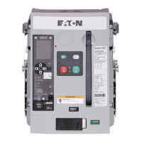
For fixed-mounted circuit breakers, secondary terminal blocks
mount onto an insulated support frame (Figure 2).
Figure 2. Fixed Terminal Block
Electrical accessory leads are tagged with numbers associ-
ated with the applicable connection diagram. Leads are also
supplied with keyed secondary connector plugs to ensure
proper connections (Figure 3).
Figure 3. Leads and Connectors (Drawout Configuration Shown)
Secondary connections are made by plugging the connector
plugs into the appropriate location. A connector plug already con-
nected can be removed by squeezing two release tabs together
with small needle nose pliers and pulling out (Figure 4).
Figure 4. Connector Plug Removal
Customer wiring is done using tension clamp terminations.
Refer to manuals MN01301001E (NF Frame) or MN01301003E
(RF Frame) for an applicable connection diagram, other spe-
cific wiring, and additional secondary contact information for
all Series NRX circuit breakers.
Section 2: Installation and removal of xed
terminal blocks
ote:N Many illustrations use the NF Frame circuit breaker for
illustrative purposes only. The RF Frame circuit breaker is handled
in a similar fashion.
Proceed with the following eight steps:
Step 1: Remove the four screws holding the front cover in
place (two on each side of the cover).
Figure 5. Step 1
Step 2: Remove the front cover. Pull down on the charging
handle to simplify removal.

 Loading...