9
Instruction Manual IB015002EN
Effective November 2021
Pow-R-Line CS switchboards
EATON www.EatonCanada.ca/PRLCS
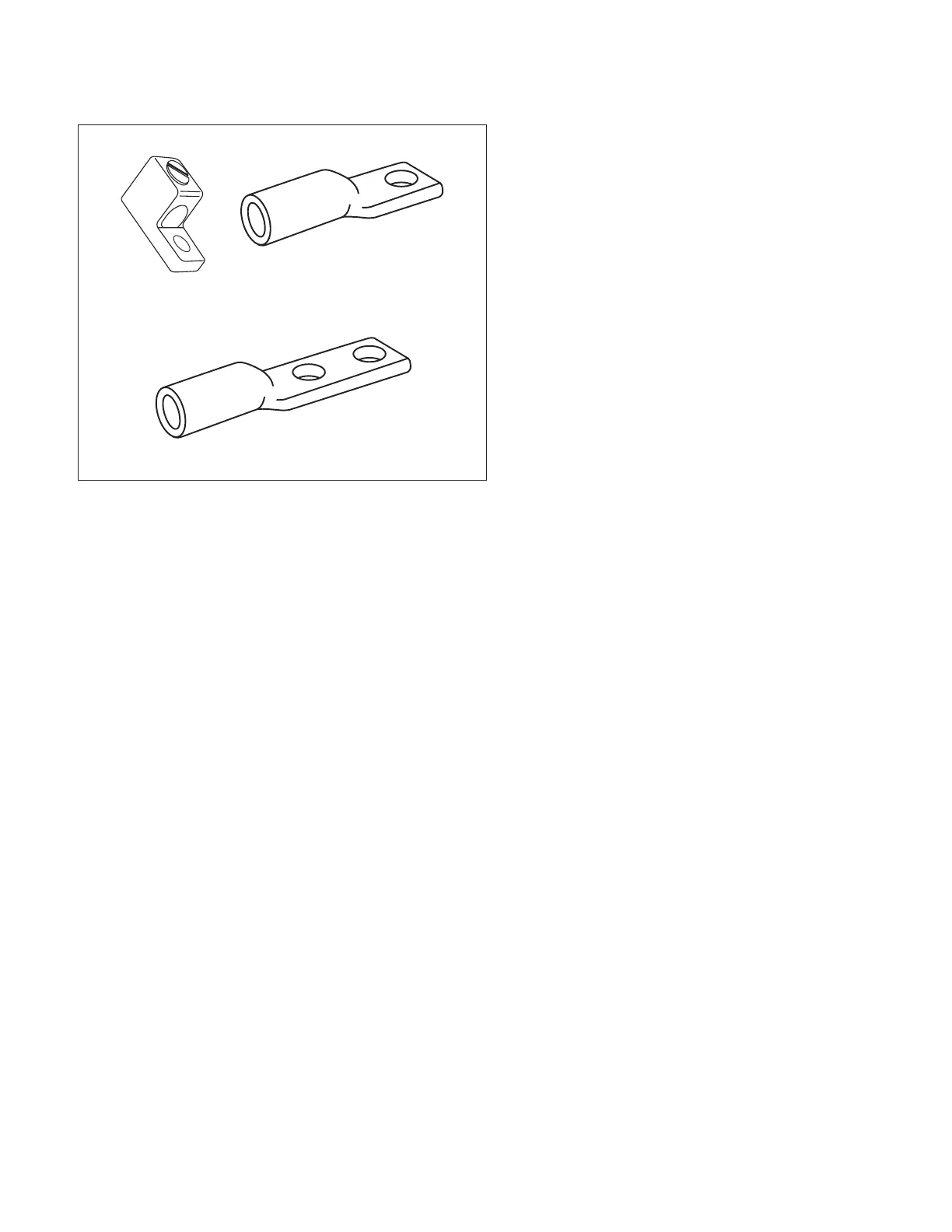
Mechanical set
Standard one-hole
Optional two-hole
Figure 15. Screw and compression lugs
Unless a switchboard specifically restricts entry to a single means
or area, cables may enter through the top, bottom, side or back of
the main incoming section. These restrictions are typically required
to conform to wire bending space requirements of the CEC. Consult
the manufacturer ’s drawings for conduit entry data.
Once the conductors are pulled inside the main section, the cables
should be formed in the space provided. Clearly identify and
segregate conductors by phase and neutral. Care should be taken
in forming insulated cables to ensure that no insulation is forced
permanently against the edges of any metal parts.
Using appropriate tools, the installer must strip the conductor
insulation sufficiently to fill the entire barrel of the connector with
bare, uninstalled conductor. Conductor must be stripped without
damage to the conductor strands. Bare strands should be of equal
length (flush) on the end cut.
Do not strip off more insulation than needed. Exposure of bare
conductor outside lug can compromise clearances.
The connector and conductor should be free of all foreign debris.
Never clip cable/wire strands in order to fit within connectors. If
cable/wire does not match the rating of the connector, contact the
manufacturer.
Mechanical set screw lugs are the most common. Use an
antioxidant compound, if required. Insert bare conductor into lug so
the bare conductor fills the full length of the lug body. Tighten lug,
then torque to levels indicated on the switchboard label.
If compression lugs are utilized and supplied with the switchboard,
the lugs will be mounted on the incoming lug pad. Remove lugs
from the pad. Use an antioxidant compound, if required. Use a
crimping tool approved for that specific lug manufacturer and lug
size. Follow instructions provided by the manufacturer of the crimp
tool.
Once the lug is affixed to the conductor, re-install the lug on the
lug pad utilizing the existing hardware. Torque hardware using
information provided on switchboard labeling. Refer to Appendix
Table 2 for torque values..
 Loading...


