EasyManua.ls Logo

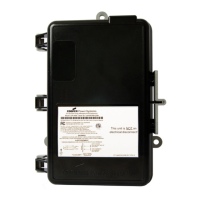
Eaton Cooper Power System LCR 6600 RFN User Manual

Eaton Cooper Power System LCR 6600 RFN
12 pages
To Next Page IconTo Next Page
Page #1 background imageLoading...
Page #1 background image
Instructional Leaflet
Technical Support: 1-800-815-2258
Introduction
This instructional leaflet contains general installation
information for the LCR 6600 RFN Load Control
Switch. The LCR 6600 RFN is used to control remote
electric loads and it is activated by commands sent
over Eaton’s Cooper Power Systems’ Radio
Frequency (RF) mesh network.
The LCR 6600 RFN uses an RF SelectCom™ module
to provide two-way communication with the
Yukon™ master station. Once powered-up, the LCR
will automatically form a communication path back
to the Yukon master station.
Advanced security features provide both over-the-air
and local port security. All local port connections and
over-the-air commands are logged to provide
traceability of actions.
The data log records the actual time of state
changes, for the control relay and appliances, to
provide improved granularity of runtime and
shedtime information.
The LCR 6600 RFN addressing must be configured
for your demand response system prior to operation.
CAUTION
Observe precautions for handling
electrostatic sensitive devices.
MISE EN GARDE
Respecter les précautions
de manipulation des dispositifs
électrostatiques sensibles.
LCR 6600 RFN
Load Control Switch (Brazil)
WARNING
Dangerous voltages are present. Equipment damage, personal injury, and death can result if safety
precautions are not followed. Use authorized utility procedures to install, test, and service the LCR 6600 RFN.
AVERTISSEMENT
Présence de tensions dangereuses. Tout défaut de se conformer aux mesures de sécurité
peut entraîner un bris d'équipement, une blessure corporelle ou même la mort. Servez-vous des procédures
autorisées par l'entreprise de services pour installer, tester et entretenir le LCR 6600 RFN.
Question and Answer IconNeed help?

Do you have a question about the Eaton Cooper Power System LCR 6600 RFN and is the answer not in the manual?

Eaton Cooper Power System LCR 6600 RFN Specifications

General IconGeneral
Operating Frequency902 to 907.5 MHz and 915 to 928 MHz License Free Band
RF Maximum Output Power30 dBm (1 W)
Data Rates38.4 kbps, 76.8 kbps and 153.6 kbps
Receiver Sensitivity-104 dBm (@ 1% PER, +25 C, 38.4 kbps) -101 dBm (@ 1% PER, +25 C, 76.8 kbps) -98 dBm (@ 1% PER, +25 C, 153.6 kbps)
ModeFrequency Hopping Spread Spectrum (FHSS)
Power Source120/240 VAC (±20%) at 50/60 Hz 24 VAC (-20%, +10%) at 50/60 Hz
Supply Output12 V ±5%, 12 W
Temperature-40º F to 131º F (-40º C to +55º C)
Relative Humidity0 to 95% non-condensing
Low PowerForm C (SPDT) non-latching
Maximum Ratings Low Current Relays1 A at 28 VDC or 120 VAC
Maximum Ratings High Current Relays30 A at 240 VAC Resistive or 28 VDC
Housing MaterialIP56 rated, injection-molded, UV-stabilized polycarbonate plastic
Rain-tightper UL916
Weight and Dimensions IconWeight and Dimensions
Box Dimensions10.81 in. H x 7.68 in. W x 3.60 in. D (27.46 cm H x 19.51 cm W x 9.14 cm D)

Summary

Introduction to LCR 6600 RFN

Safety Information and Definitions

Safety Instructions

General caution and warning statements applicable to the equipment.

Hazard Statement Definitions

Defines DANGER, WARNING, and CAUTION statements used in the manual.

Regulatory Notices

End Product Labeling Requirements

Requirements for labeling the final product with FCC and IC information.

Features and Functions Overview

Installing Jumpers for Digital Control

Mounting the LCR 6600 RFN

LCR 6600 RFN Installation Steps

Wiring Connections and Test Button

Test Button Functions

Explains the Test button's functions for canceling cold load pickup and testing relay control.

LCR 6600 RFN LED Indicators

LCR Unit LEDs

Describes the meaning of the Red (Load Status) and Green (Power) LEDs on the LCR unit.

RF SelectCom Module LEDs

Details the meanings of the Blue and Green LEDs for the RF SelectCom module.
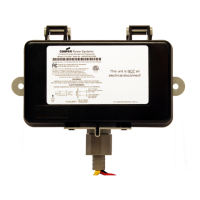
LCR 6600 RFN Specifications

Related product manuals