Do you have a question about the Eaton Cutler-Hammer SPB and is the answer not in the manual?
Crucial safety instructions and warnings to prevent injury and equipment damage during operation.
Legal disclaimer regarding product information, warranties, and limitations of liability.
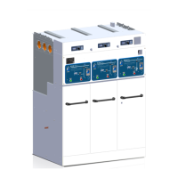
Details on the physical design, construction, and internal arrangement of the transfer switch.
Overview and categorization of different types of automatic and non-automatic transfer switch equipment.
A guide to interpreting the product's catalog number for specific configurations and features.
Procedures for inspecting and verifying the condition of the transfer switch upon delivery.
Guidelines and precautions for safely moving and transporting the transfer switch equipment.
Recommendations for proper indoor storage of the equipment to maintain its integrity and warranty.
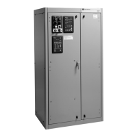
A general overview of the transfer switch equipment, noting its single configuration and enclosure.
Details of the power panel, including main contacts, transfer mechanism, and load connections.
Explanation of the insulated case switches acting as main contacts for power source connection.
Description of how load side contacts are interconnected via a common bus bar assembly.
Information regarding the stored-energy mechanism used for transferring power between sources.
Details of the multi-tap transformer panel enabling voltage selection for the system.
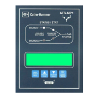
Explanation of the logic panel's function in monitoring power sources and controlling transfer operations.
Information on the 100-percent-rated neutral connections provided with the transfer switches.
Description of various optional features available for enhancing the transfer switch functionality.
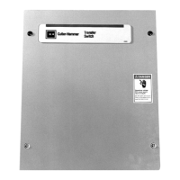
Details regarding the rugged steel enclosure, including its mounting and door features.
Information on the applicable NEMA, UL, and other industry standards the equipment adheres to.
A general overview of the factory-wired and tested transfer switch installation requirements.
Guidance on selecting a suitable, flat, and rigid mounting location for the transfer switch.
Step-by-step instructions for safely unpacking and physically mounting the transfer switch enclosure.
Detailed procedures and warnings for correctly connecting power cables to the transfer switch.
Instructions for setting and calibrating the voltage selection panel before service.
General wiring information and safety precautions for connecting control and power circuits.
Specific instructions for connecting engine start wires to the designated terminal blocks.
Information on connecting alarm contacts for remote alarming capabilities.
General overview of the transfer switch's main contacts and stored-energy transfer mechanism.
Detailed explanation of the automatic transfer sequence, including power source failures and restorations.
Procedures for performing mechanical and electrical tests on the transfer switch equipment.
Comprehensive guide to diagnosing and resolving common operational issues with the transfer switch.
Steps to troubleshoot when the transfer switch shows no signs of operation or response.
Troubleshooting steps for when the switch fails to revert to the normal power source.
Troubleshooting steps for when the switch fails to transfer to the emergency power source.
Steps to diagnose and fix issues related to the automatic recharging of the switching mechanism.
Introduction to the importance of regular inspection and maintenance for the transfer switch.
Outlines a suggested schedule and actions for performing periodic maintenance on the equipment.
| Poles | 2, 3 |
|---|---|
| Amperage | 100A |
| Voltage | 240 VAC |
| Interrupting Capacity/Rating | 22kA |
| Standards | CSA Certified |