19
LCD touchscreen display programming
PRC-E Series Instruction Manual MN014003EN August 2015 www.eaton.com
Table 2 shows the default settings that will be applied to
the connected BCBs in 42-circuits panelboards.
Table 2. Default BCB Addressing Auto-Configuration
Address Type Panelboard Name
1 Left 1 PNL1
2 Right 1 PNL1
3 Left 2 PNL2
4 Right 2 PNL2
5 Left 3 PNL3
6 Right 3 PNL3
7 Left 4 PNL4
8 Right 4 PNL4
If required, these default settings can be edited to meet the
current panelboard layout.
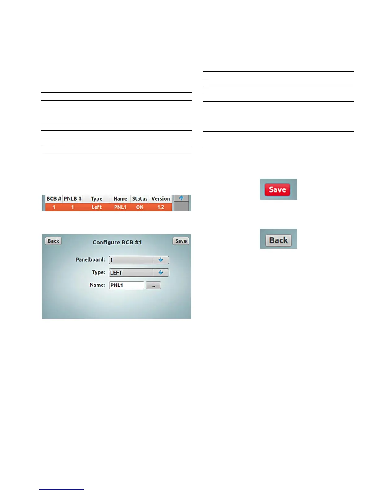
To edit the configuration of a BCB, in the “Panelboard
Configuration” screen, tap the row of the BCB.
This will display the “Configure BCB…” screen.
In this screen, the “Panelboard” number, “Type” (position),
and “Name” can be edited. If any changes are made in this
screen, the “Save” button will turn “red” to signify that
changes need to be saved.
The “Panelboard” number can be 1 through 8, the “Type”
depends on the BCB position and type of panelboard and
the “Name” can be any 4-character alphanumeric input for
the panelboard identification. See the list of panelboard
types and their descriptions for details.
Table 3. Panelboard Types
Type Circuit Breaker Numbers Panelboard
Left Odd-numbered (1–41) 42-circuit
Right Even-numbered (2–42) 42-circuit
Left-18 Odd-numbered (1–17) 18-circuit
Right-18 Even-numbered (2–18) 18-circuit
Left-30 Odd-numbered (1–29) 30-circuit
Right-30 Even-numbered (2–30) 30-circuit
Top Sequential (1–21) 30 and 42-circuit column
Bottom Sequential (22–42) 42-circuit column
Top-9 Sequential (1–9) 9-circuit column
Bottom-30 Sequential (22–30) 30-circuit column
Once all the BCB configuration edits are complete, tap the
red “Save” button to save the changes or the Back button to
disregard changes.
To leave the page without saving changes, just tap the
“Back” button.
Tap the “Back” button to return to the “Panelboard
Configuration” screen.
Once all the panelboard configuration edits are complete,
the “Discover Breakers” command must be initiated.
Discover breakers
The controllable circuit breakers in the panelboards must be
discovered by the PRC-E controller. The “Discover Breakers”
command must be initiated at the commissioning of the
system, after any addition of controllable circuit breaker(s) in
a panelboard(s), after any addition of PRCEP panelboard(s) to
a system or after a panelboard configuration change. During
this discovery process, the BCBs in the master panelboard,
and all PRCEP panelboards connected to it, will be scanned
for the presence of controllable circuit breakers. The presence
of each controllable circuit breaker is captured and stored in
the controller’s database. The BCB addressing is critical for
this process to be successful. In the Master and Expansion
panelboards, each BCB should have a unique address of 1–8.
See the “BCB addressing” section on page 48.