38
PTO Interface
PTO Interface
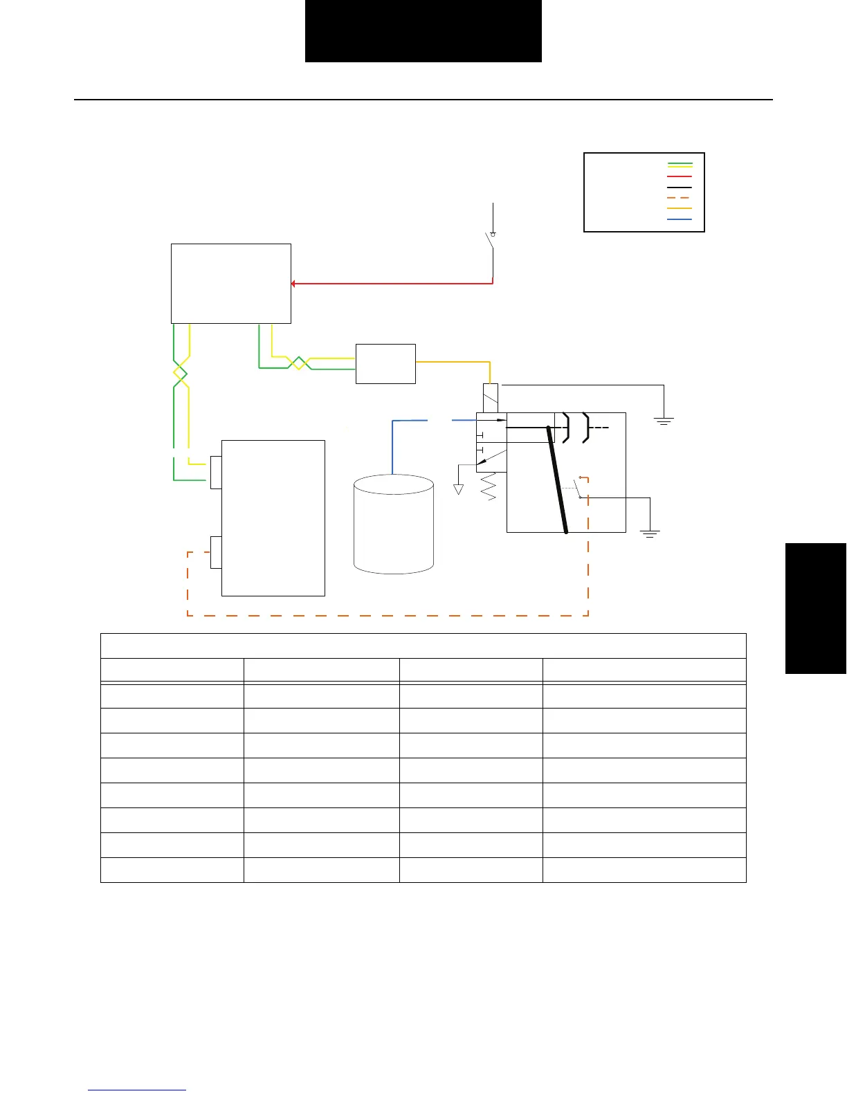
PTO Wiring Diagrams
PTO Switch
OEM ECU
TCM
Vehicle
Connector
Body
Connector
16
Air Tank
Air
Supply
1. Request from PTO Switch
to OEM ECU
3. TCM sends Engage
message via J1939 to
OEM ECU
4. OEM ECU Proprietary
Engage signal to the
Chassis Module to actuate
the PTO Air solenoid
5. Confirm ground signal
from ball switch hardwired
to TCM
PTO
1112
J1939 PTO Installation with Hardwire Confirm
Module
2. OEM ECU sends the
Request message via J1939
to the TCM
J 1939 =
Battery Voltage =
Ground =
Switched Ground =
Solenoid Driver =
Air Supply =
J1939 PTO Control with Hardwire Confirm
From To Description Notes
PTO Switch OEM ECU PTO Request Hardwired
OEM ECU TCM PTO Request J1939
TCM OEM ECU PTO Engage J1939
OEM ECU OEM Module PTO Engage J1939
OEM Module PTO Solenoid Solenoid PWR 12 Volt
PTO Solenoid Chassis GND Solenoid GND
PTO Confirm Switch TCM B-16 PTO Confirm 5 Volt
PTO Confirm Switch Chassis GND PTO Confirm
 Loading...