Page 6 (60) Motor Pump Enhanced Protection Application SV9000
Analog input scaling, parameters 2.11—2.14 are not used when joystick control is
used.
F
out
–10V
+10V
V
in
F
max
(Par. 1.2)
F
max
(Par. 1.2)
F
min
(Par. 1.1)
F
min
(Par. 1.1)
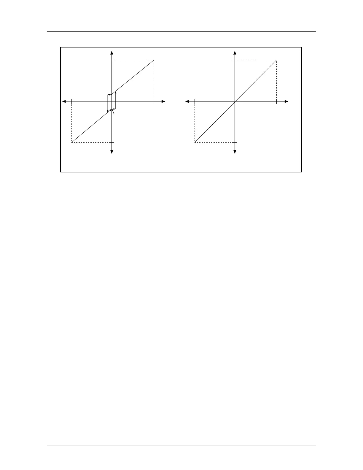
Hysteresis ±2% (±0.2V)
If minimum frequency (Par. 1.1) > 0,
hysteresis is ±2% at the reversing point.
F
out
–10V
+10V
V
in
F
max
(Par. 1.2)
F
max
(Par. 1.2)
If minimum frequency (Par. 1.1) = 0,
there is no hysteresis at the reversing point.
Figure 5.2-1: Joystick Control V
in
Signal -10 V—+10 V
8 Reference value is changed with digital input signals DIA4 and DIA5.
- switch in DIA3 closed = frequency reference increases
- switch in DIA4 closed = frequency reference decreases
Speed of reference change can be set with parameter 2.15.
9 Same as setting 8 but the reference value is set to the minimum frequency (par. 1.1)
each time the frequency converter is stopped.
10 Same as setting 8 but the reference is stored to the memory over utility break. When
the value of the parameter 1.5 is set to 8, 9 or 10, the value of the parameters 11.4
and 11.5 is automatically set to 11.
11 The smaller of signals V
in
and I
in
is the frequency reference
12 The greater of signals V
in
and I
in
is the frequency reference
13 Panel reference r1 is the frequency reference
1.6 Jogging speed reference
Parameter value defines the jogging speed selected with the digital input.
1.7 Current limit
This parameter determines the maximum motor current from the frequency converter. To
avoid motor overload, set this parameter according to the rated current of the motor.

 Loading...


