5
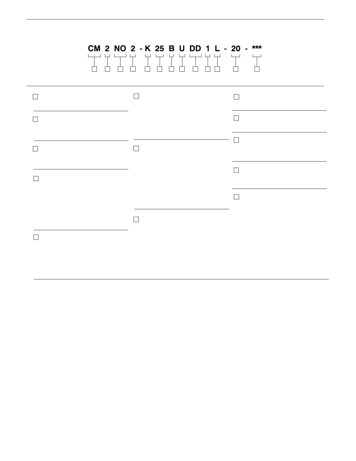
U Section - No Spool
(For Series Operation)
9
6
Inlet Body Type
R - Standard relief valve
(Partial flow by-pass)
F - Tandem inlet valve
(Full flow by-pass)
K - Standard relief valve
(Full flow by-pass)
7
Relief Valve Settings
05 - 500 psi
07 - 750 psi
10 - 1000 psi
12 - 1250 psi
15 - 1500 psi
17 - 1700 psi
20 - 2000 psi
22 - 2250 psi
25 - 2500 psi
Special Features
Spool Modification
1 - Detent
1
2
3
Series Designation
2 - 2 series
3 - 3 series
Valve Bank Modifications
N - Standard sections
O - No modifications
Table 2. Model Code Breakdown
4
Port Connections CM2 Series
1 - 1.3/16-12 inlet & cyl. ports
1.5/16-12 outlet ports
2 - 1.5/16-12 inlet & cyl. ports
1.5/8-12 outlet ports
4 - 1.5/8-12 inlet & outlet ports
1.5/16-12 cyl. ports
5
Port Connections CM3 Series
1 - SAE 1” 4 bolt flange
2 - 1.5/16-12 inlet & cyl. ports
1.5/8-12 outlet ports
4 - 1.5/8-12 inlet & cyl. ports
1.7/8-12 outlet ports
13
Directional Control
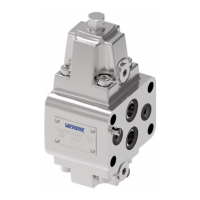
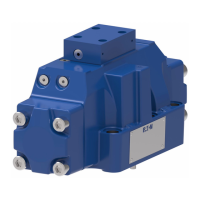
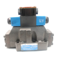
CM - Multiple unit valve, mobile
35671 2 98 10 11 12 13
Model Code
Design & Modification
20- Second design, no modification
30- Third design, no modification
12
4
8
Spools
B - Motor spool
C - Float spool
D - Double acting
T - Single acting
10
Outlet Body
L - Standard Outlet
E - Tandem Outlet
11
 Loading...