10
6
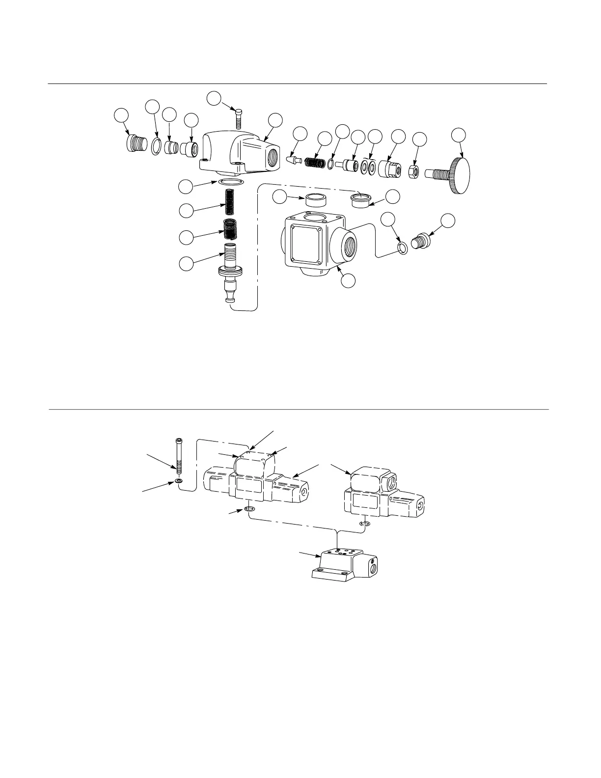
Figure 5. -50 Design Relief Valves
(1) Knob
(2) Locknut
(3) Retainer
(4) Spacer
(5) Plunger
(6) Seal
(7) Spring
(8) Poppet
(9) Plug
(10) Seal
(11) Restriction Plug
(10 size only)
5
4
3
22
23
1
15
14
2
16
17
18
19 20
11
13
12
7
8
9
10
(12) Seat
(13) Screw
(14) Cover
(15) Seal
(16) Spring (Omitted on C*-H06-**-50 model)
(17) Spring (High-vent V’ models)
(18) Piston
(19) Seat
(20) Sleeve (High-flow ’H’ models)
(21) Body
(22) Plug
(23) Seal
21
Figure 6. C*5 Solenoid Controlled Relief Valve
(a) Screw (4)
(b) Name Plate
(c) Directional Valve Cover
(d) Screw (4)
(e) Directional Valve
(f) Relief Valve Cover
(g) Seals
(a)
(b)
(c)
(d)
(e)
(f)
(g)
Washers (4)
 Loading...