5
Section III – Principles of Operation
A. Pressure Relief
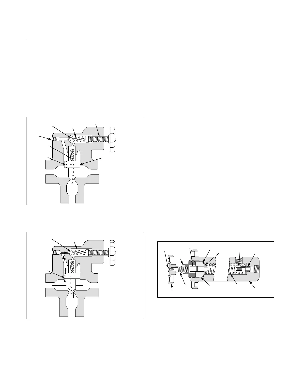
Figure 1 illustrates the basic valve operation. The valve pres-
sure setting is determined by the adjusting screw position
which varies the heavy spring compression. The balanced
piston is normally held against the seat by the light spring.
System pressure is present in chamber A and is connected
to chamber B through orifice C.
The closed position of the valve is shown in Figure 1A. With
system pressure less than the valve setting, the pilot poppet
is held against its seat by spring force. Pressures in cham-
bers A and B equalize through orifice C. Thus, the piston is
hydraulically in balance and held against its seat by the light
spring.
Figure 1A.
Poppet
Balanced
Piston
A
Vent
Connection
Light
Spring
Orifice
Heavy
Spring
Adj. Screw
(System Pressure)
To
Tank
A
C
In Figure 1B the valve is shown throttling fluid to the tank
port. This occurs when system pressure exceeds the heavy
spring setting and forces the poppet away from its seat.
Figure 1B.
Poppet
A
Orifice
To
Tank
B
C
D
B
Fluid then flows through orifice C and chamber B, past the
poppet into chamber D, and down through the drain hole in
the center of the piston to the tank port.
The pressure in chamber B is limited by the setting of the heavy
spring. When pressure in chamber A exceeds chamber B
sufficiently, pressure unbalance overcomes the force of
the light spring and lifts the piston. Excess fluid then flows past
the bottom of the piston to tank.
When the system pressure drops below the valve setting,the
poppet reseats. Control flow through orifice C stops and
pressures in chambers A and B are again effectively
equalized.
The light spring then forces the piston toward the seat while
orifice C continues to equalize pressure between chambers
A and B. When the balance piston is closed against its seat,
all flow through orifice C stops.
B. Venting
The ”High-Vent” option (”V” in the model code) is used when
it is necessary to maintain pilot pressure for other valves in
the system. This option provides a faster valve de-venting
(closing) action. Higher pressure (approximately 80 PSIG) is
maintained when the valve is vented because a heavier
piston spring is used.
Relief valves can be vented to unload pump delivery to tank in
the following manner:
Connect a shut-off valve to the vent port of the main relief valve.
Chamber ’B’ above the balanced piston can be opened to tank
(see Figure 1B). This removes pressure at the top of the
balanced piston. Pressure in chamber ’A’ overcomes the light
spring, unseats the balanced piston, and diverts all pump
delivery to tank.
A solenoid controlled directional valve (C*5) may be used
to vent flow to tank. This directional valve is mounted on top
of a standard relief valve to form a single package. See
Figure 6.
C. Remote Control
The main relief valve may be adjusted from a remote location
by using another adjustable valve similar in function to the
main relief valve pilot stage (see Figure 2.) Flow past the
poppet of the remote control valve is directed to tank. The
following rules should be maintained for optimum results:
Figure 2.
Poppet
Plunger
Lock
Nut
Seat
O-ring
Guide
Body
Spring
Retainer
Adj.
Screw
Knob
Screw
1. Keep hydraulic lines (tubing) as short as possible.
2. Set main relief valve 200-300 PSIG above maximum
operating pressure. DO NOT exceed the valve pressure rating.
3. Set remote control valve to maximum operating
pressure.
4. Check system for stability characteristics. If the system
is unstable, reduce the line length and/or proceed to step 5.
5. Install an orifice in the vent opening of the main relief
valve cover and in the pressure port of the remote control valve.
DO NOT go below 0.040 inch diameter or a malfunction could
result. Orifices should be as large as possible to prevent exces-
sive pressure drop and still maintain noise free operation.
 Loading...