35
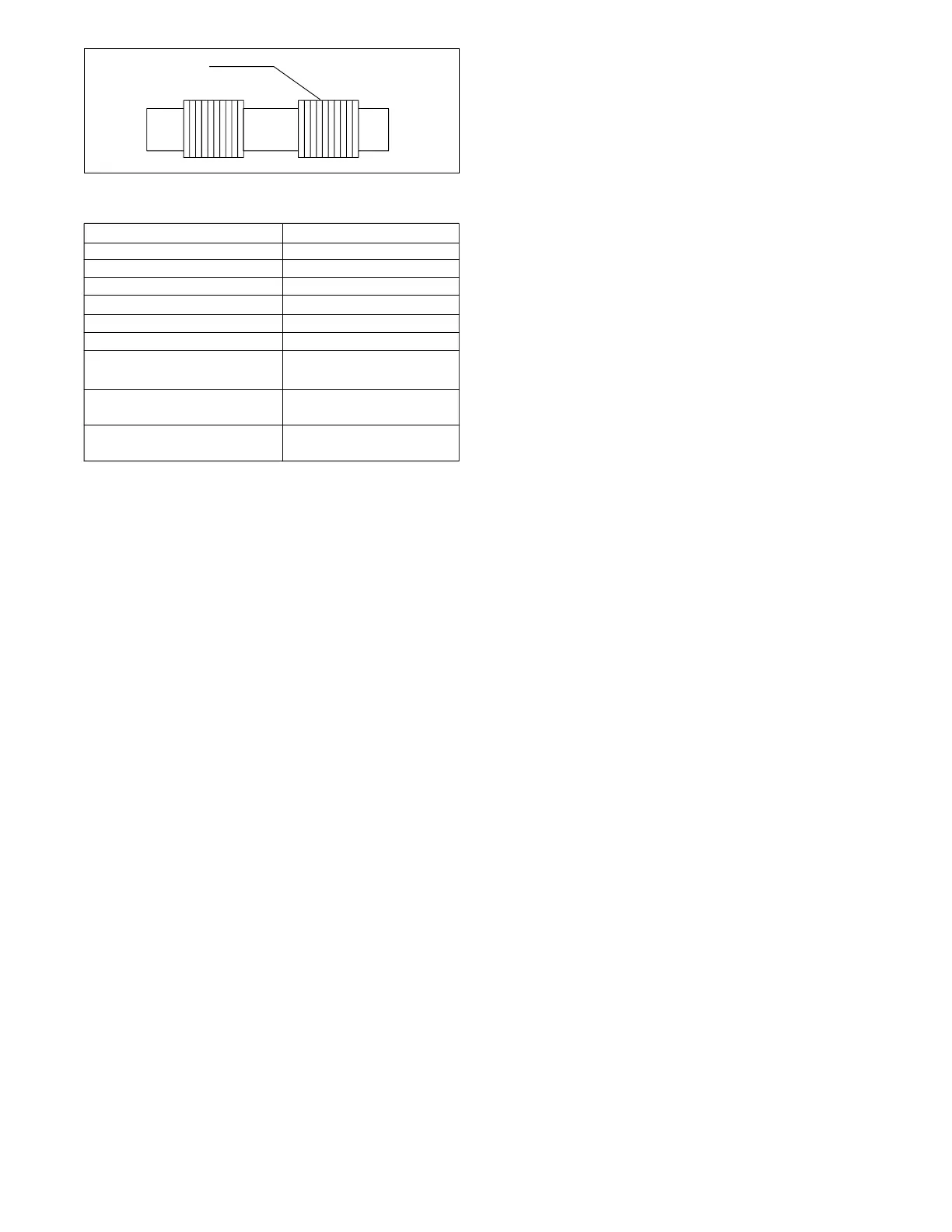
Land Balancing
Grooves
Figure 22. Spool Balancing Grooves
Voltage
6 DC 1.5 Ohms
12 DC 5 Ohms
24 DC 24 Ohms
48 DC 80 Ohms
115 DC 480 Ohms
230 DC 1800 Ohms
115 AC
(60 Hz)
230 AC
(60 Hz)
460 AC
(60 Hz)
Coil Resistance
Table 7. Coil Resistance
13 Ohms
50 Ohms
204 Ohms
H. Assembly
Before assembly, obtain the correct seal kit as noted in the
parts drawing. Lubricate all O-Rings and internal parts with
clean system fluid to provide initial lubrication and facilitate
assembly.
Check the model code to determine correct assembly of
units. If a L.H. suffix appears in the model code, the pilot
valve solenoid is assembled left hand. In such cases, all pilot
valve parts are reversed except the body and spool.
Assembly will be in reverse of the disassembly sequence
shown in Figures 15 and 18 unless otherwise indicated.
1. Assembly of Main Stage Section
Refer to Figure 15.
a. Install O-Rings on construction plugs. Lubricate
plug threads and install plugs into body (6). Torque plugs to
value noted in parts drawing. Refer to Table 1.
b. Tap new rest pin(s) (25) into place if removed
during disassembly.
NOTE
The following step (c) pertains to integral check
valve models only.
c. Place spring (23) into poppet (22) and then install
the poppet into pressure port (P) cavity as shown. Obtain a
suitable push rod and press seat (21) (large diameter face
up) into pressure port (P) cavity. Use an arbor press for this
operation. Install O-Ring (20) into pressure port mounting
groove.
d. Install O-Rings (19) into “X” and “Y” port mounting
grooves.
e. Install O-Rings (18) into port mounting grooves
“A”, “B” and “T”.
f. Lubricate spool lands with clean system fluid and
then carefully install spool (17) into main body bore. Make
sure the spool moves freely inside the body bore and is
oriented properly. (See parts drawing.)
g. Install washer (16) and spring (15) on end of spool
(17). (NOTE: Spring (15) and washer (16) do not exist on
spring offset “A” or “floating” type models.)
h. Install O-Ring (14) into cover (13) as shown.
i. Fasten cover (13) to end of body (6) with four
screws (12). Torque the screws (12) to value note in parts
drawing. Make sure cover is oriented properly (in line with
body contours).
j. If applicable, install washer (11) and spring (10) on
opposite end of spool. (NOTE: Spring (10) and washer (11)
do not exist on “A” or “floating” type models).
k. Install O-Ring (9) into cover (8).
l. Fasten cover (8) to end of body with four screws
(7). Torque screws to value shown in parts drawing.
2. Assembly of Pilot Valve Section
Refer to Figure 18.
a. Spring centered “B” and “C” models:
1. Install O-Ring (35 and 37) on plugs (34 and 36).
Lubricate plug threads and install into body (38) as shown.
Torque plugs to the value shown in part drawing. See Table 1.
2. Lubricate pilot spool (33), then carefully install
spool into the body bore.
3. Assemble washer (32) on end of spool (33) with
sharp break edge toward outside of body.
4. Install spacer (31) on end of pilot spool with
spacer counterbore facing push pin (25).
5. Install spring (30) into body bore.
NOTE
The following steps (6 through 8) pertain to spring
centered “B” models only.
6. Assemble O-Ring (19a) on cover (18a), then
assemble cover to valve body (38) with screws (17a). Torque
screws to the value shown in parts drawing.
7. Install washer (16) on end of valve spool with
sharp break edge toward outside of valve.
8. Install spring (14) into body cavity over washer.
NOTE
The following steps (9 thorough 16) pertain to
spring centered “C” models only. If your valve is
equipped with serviceable core tub S/A (W3),
perform step (9). Omit step (9) if your model has
nonserviceable core tubes (W). Non serviceable
core tubes CANNOT be disassembled.
9. Install O-Ring (29) on manual plunger (28).
Lubricate plunger (28) and O-Ring (29) with petroleum jelly.
a. Insert manual plunger (28) into the hole at
the bottom of core tube (24) with the shoulder of the plunger
on the inside of the core tube.
 Loading...