InstructionBook
Page 46
IB131009EN
Figure 6-20 Place Tape on Right Side Panel of
Breaker
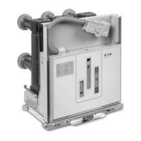
Figure 6-23 Typical Circuit Breaker Front View with
CloSure
TM
Tool Attached (approximate mechanism
chassis width)
Table 6.3 Closure
TM
Circuit Breaker Type
Tool Mounting/Testing Locations by
Figure 6-21 Illustrative Testing Tape Sample
Figure 6-22 Front View of CloSure
TM
Tool Showing
Mounting/Testing Hole Locations (6352C49H01)
-1
-2
-3
-4
C-2
C-1C-3 C-4 C-5
C-6
B-1
B-2
Width
B
* Figure not to scale
* Note: Use the
center
of the marker
diameter
to determine “X”
distance
8.0 to 10
inches
“X” Inches
CloSure
TM
Overtravel
CloSure
TM
Distance
CloSure
TM
Position
A
C
5 3/16” Approx
Date, # of Breaker Operations, CloSure
TM
Distance
Date, # of Breaker Operations, CloSure
TM
Distance
Breaker
Line
pproximate
Mechanism
Cabinet
Width (inch)
Upper
Mounting
Hole
Lower
Mounting
Hole
Marker
Placement
Hole
DHP-VR
20
27
A1
A1
B2
B1
C2
C5
VCPW-ND
20/21
A1
B2
C2
VCP-W
27
33
A1
A2
B2
B2
C5
C6
VCP-WR
18
A1
B2
C1
20
A1
B2
C2
27
A1
B2
C5
W-VAC,
W-VACR
18
A1
B2
C1
25
33
A1
A2
B1
B2
C4
C6
 Loading...