Do you have a question about the EAW CXA240 and is the answer not in the manual?
Essential safety precautions for operation, handling, environment, and connections.
Critical warnings regarding electric shock, fire, moisture, and hazardous voltages.
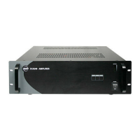
CXA240 amplifier's purpose, performance, input/output options, and power requirements.
Amplifier's features, connectivity, power, and suitability for various sound reinforcement scenarios.
Explanation of status LEDs: protection, signal presence, and peak output.
Details on monitoring output signal strength and avoiding clipping with the LED meter.
Description of the rocker-style AC mains power switch on the front panel.
Importance of airflow for the fan-cooled amplifier to prevent overheating.
Instructions for setting the AC voltage (115V/230V) before connecting power.
Details on the power cord connection and checking AC mains compatibility.
Location and replacement instructions for the AC fuse, emphasizing safety.
Chassis ground connection via AC ground and professional wiring needs.
Functionality of the DC switch for automatic failover to external battery backup.
Location and replacement of the DC fuse for protecting the DC rail supply.
Connecting an external 24 VDC battery for backup power, including wiring and usage.
Instructions for connecting speakers using the 4 Ω output terminal.
Guidance for 70 V or 100 V systems, including transformer requirements.
Description of the control used to adjust the incoming audio signal level.
Details on connecting unbalanced audio sources like tuners or CD players via RCA.
Using combination inputs for balanced XLR or 1/4" TRS/TS plugs for line-level sources.
Importance of adequate airflow for the fan-cooled amplifier to prevent overheating.
Guidelines for rack mounting the unit, including support requirements.
Standard wiring configuration for XLR connectors (Pin 1 Shield, Pin 2 Hot, Pin 3 Cold).
Description of TRS connectors for balanced signals and stereo headphones.
Description of TS connectors for unbalanced signals.
Explanation of RCA connectors, commonly used for unbalanced audio signals.
Illustrative diagram showing how to connect speakers, backup battery, and audio sources.
Key performance metrics: power output, frequency response, distortion, and noise.
Input types, sensitivity, impedance, output options, and control functions.
Unit dimensions, weight, and warranty period and coverage details.
Instructions for obtaining technical support and arranging for warranty service.
Explanation of what is covered by the warranty and what is excluded.
Specific exclusions from warranty coverage, such as damage from misuse or unauthorized modifications.
| Channels | 2 |
|---|---|
| Signal-to-Noise Ratio | > 100 dB |
| Input Impedance | 20 kOhm balanced |
| Power Output @ 4 ohms | 240W per channel |
| Frequency Response | 20Hz - 20kHz (±0.5dB) |