CXA240 – 5
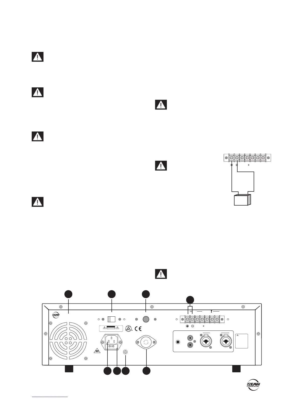
4. REAR PANEL FEATURES
4. COOLING FAN
These vents should not be obstructed, or this may
cause overheating.
5. VOLTAGE CONVERSION
The unit can be congured to operate at 115 VAC or 230 VAC.
Be sure this switch is set to the correct position for
the AC power supply being used, before plugging in
the power cord. The switch can be moved with a small at
screwdriver, once the protective cover is removed. Replace
the cover afterwards.
6. IEC AC INPUT
The supplied power cord connects here. Check that
the voltage setting of the VOLTAGE CONVERSION (5)
switch is the same as your local AC Mains voltage before
plugging in the power cord. Make sure that your local AC
Mains is capable of supplying adequate current, and has a
protective earthing connection.
7. AC FUSE
The fuse resides inside a little cover just below the AC
input.
Make sure that the power cord is unplugged before
removing the AC fuse. When you are sure that all is
safe, pry off the fuse cover with a at screwdriver, taking
care not to damage the cover or fuse. Replace the fuse only
with the same type and rating as marked on your unit.
8. GROUND (EARTH) SCREW
The chassis connects to ground via the AC ground, and
normally does not need any extra ground connection.
Connections, if required, should be made by experienced,
qualied electricians.
9. DC POWER SWITCH
If this switch is pressed in, the unit will automatically
switch to external DC battery power whenever (or if-ever)
your local AC power fails. You will need to connect an
external 24-volt battery to the DC battery terminals (11).
If the switch is out, the battery will not power up the unit.
10. DC FUSE
The DC fuse resides inside this fuseholder. The fuse offers
protection to the DC rail supply to the power amplier.
Make sure that the AC supply is turned off before
removing the fuse. When you are sure that all is safe,
press in the fuse cover and turn it counter-clockwise.
Replace the fuse only with the same type and rating as
marked on your unit.
11. DC BATTERY TERMINALS
These two screw terminals are used to connect an optional
external 24 VDC battery.
Make absolutely sure
the positive post of your
battery goes to the positive
terminal, and the negative
post connects to the negative
terminal. To minimize the
voltage drop across the wires
and prevent overheating, use at
least 14 AWG wire.
The unit can be powered using a 24 VDC power supply
(if the rear panel DC POWER SWITCH is pressed in). This
serves as a backup supply in case of an AC power failure.
The unit seamlessly switches to the backup supply if
there's a power loss, allowing safety instructions and
emergency communications to continue. When both AC
power and 24 VDC power are connected, the AC power is
used and no current is drawn from the DC supply.
Note: The unit will not charge the battery, so you
should have a dedicated charging system. Note also,
that when running on DC power, the output is lower than
when running on AC power.
POWER
OUTPUT
CXA240 - AMPLIFIER
PEAK
PROT
SIGNAL
DC FUSE
CAUTION : SHOCK HAZARD-DO NOT OPEN
RISK OF FIRE-REPLACE FUSE AS MARKED.
RISK OF ELECTRIC SHOCK
DO NOT OPE
N
GND
FUSE
OFFON
IV/10K BAL.
DC POWER
LINE
LEVEL
ADJUST
TO REDUCE THE RISK
OF FIRE OR ELECTRI
C
SHOCK, DO NOT EXPOSE
THIS AP PARATUS TO
RAIN OR MOISTURE.
RISK OF HAZARDOUS
ENERGY! MAKE PROPER
SPEAKER CONNECTION.
SEE INSTRUCTIONS
BEFORE USING!
WARNING
INPUT
6.3AL 250V
MANUFACTURED IN CHINA © 2004 LOUD TECHNOLOGIES INC.
"EAW" IS A REGISTERED TRADEMARK OF LOUD TECHNOLOGIES INC.
COM COM 70V 100V
4
OUTPUT
DC 24V
CAUTION
CXA240 - AMPLIFIER
115VAC/230VAC~ 60Hz/50Hz
115VAC/230VAC~ 60Hz/50Hz
115
F
U
S
E
F
U
S
E
F
U
S
E
PUSH PUSH
-+
24VDC
6
4
5
9
11
7
10
8