EasyManua.ls Logo

ebm-papst 8300100075 - User Manual

ebm-papst 8300100075
16 pages
Print Icon
To Next Page IconTo Next Page
Loading...
Operating instructions
8300100075
VBH0450CTTPS
Translation of the original operating instructions
ebm-papst Mulfingen GmbH & Co. KG
Bachmühle 2
D-74673 Mulfingen
Phone +49 (0) 7938 81-0
Fax +49 (0) 7938 81-110
info1@de.ebmpapst.com
www.ebmpapst.com
CONTENTS
1. SAFETY REGULATIONS AND INFORMATION
11. SAFETY REGULATIONS AND INFORMATION
Read these operating instructions carefully before starting work on the
device. Observe the following warnings to prevent malfunctions or
danger to persons.
These operating instructions are to be regarded as part of the device.
The device is only to be sold or passed on together with the operating
instructions.
These operating instructions may be duplicated and distributed to inform
about potential dangers and their prevention.
1.1 Hazard levels for warnings
11.1 Hazard levels for warnings
These operating instructions use the following hazard levels to indicate
potentially hazardous situations and important safety regulations:
DANGER
Indicates an imminently hazardous situation which will result in
death or serious injury if the specified actions are not taken.
Compliance with the instructions is imperative.
WARNING
Indicates a potentially hazardous situation which can result in
death or serious injury if the specified actions are not taken.
Exercise extreme caution while working.
CAUTION
Indicates a potentially hazardous situation which can result in
minor or moderate injury or damage to property if the specified
actions are not taken.
NOTE
A potentially harmful situation can occur and, if not avoided, can
lead to property damage.
1.2 Staff qualifications
11.2 Staff qualifications
The device may only be transported, unpacked, installed, operated,
maintained and otherwise used by suitably qualified, trained and
authorized technical staff.
Only authorized specialists are permitted to install the device, to carry
out a test run and to perform work on the electrical installation.
1.3 Basic safety rules
11.3 Basic safety rules
The safety hazards associated with the device must be assessed again
following installation in the final product.
The locally applicable industrial safety regulations are always to be
observed when working on the device.
Keep the workplace clean and tidy. Untidiness in the work area
increases the risk of accidents.
Note the following when working on the device:
; Do not perform any modifications, additions or conversions on the
device without the approval of ebm-papst.
WARNING
To reduce the risk of fire, electric shock or injury to people, do
not use any replacement or add-on parts that have not been
approved by ebm-papst (e.g. parts manufactured with a 3D
printer).
21.4 Voltage
21.5 Safety and protective features
21.6 Electromagnetic radiation
21.7 Mechanical movement
21.8 Emissions
21.9 Hot surface
21.10 Transport
31.11 Storage
32. INTENDED USE
43. TECHNICAL DATA
43.1 Product drawing
53.2 Nominal data
53.3 Data according to Commission Regulation (EU) 327/2011
53.4 Technical description
63.5 Mounting data
63.6 Transport and storage conditions
63.7 Electromagnetic compatibility
64. CONNECTION AND STARTUP
64.1 Mechanical connection
74.2 Electrical connection
84.3 Connection in terminal box
104.4 Connection diagram
114.5 Configuration options
124.6 Equivalent circuit diagrams
134.7 Checking connections
134.8 Switching on the device
134.9 Switching off the device
134.10 Suppression of speed ranges
135. INTEGRATED PROTECTIVE FEATURES
146. MAINTENANCE, MALFUNCTIONS, POSSIBLE
CAUSES AND REMEDIES
146.1 Warning/status codes
156.2 Vibration testing
156.3 Cleaning
166.4 Safety inspection
166.5 Disposal
Item no. 1170000665 · ENU · Change 262664 · Approved 2022-10-26 · Page 1 / 16
ebm-papst Mulfingen GmbH & Co. KG · Bachmühle 2 · D-74673 Mulfingen · Phone +49 (0) 7938 81-0 · Fax +49 (0) 7938 81-110 · info1@de.ebmpapst.com · www.ebmpapst.com
Question and Answer IconNeed help?

Do you have a question about the ebm-papst 8300100075 and is the answer not in the manual?

Summary

Safety Regulations and Information

Hazard Levels for Warnings

Explains hazard levels (DANGER, WARNING, CAUTION) and their meanings.

Basic Safety Rules

Outlines fundamental safety rules, workplace cleanliness, and restrictions on modifications.

Voltage

Addresses electrical safety concerning voltage, including precautions for charged devices.

Mechanical Movement

Warns about risks from rotating parts, entanglement, and ejected components.

Intended Use

Improper Use

Lists prohibited operations and potential hazards associated with misuse.

Technical Data

Nominal Data

Lists essential technical specifications like voltage, current, speed, and power.

Connection and Startup

Mechanical Connection

Guides on securely connecting the device mechanically, avoiding damage and ensuring proper fit.

Electrical Connection

Details essential safety precautions and steps for making electrical connections to the device.

Supply Connection and Fuses

Specifies fuse assignments, cable cross-sections, and voltage ranges for supply connection.

Connection in Terminal Box

Guides on preparing cables and connecting them within the terminal box.

Connect Cables to Terminals

Step-by-step instructions for connecting wires to the device terminals.

Connection Diagram

Illustrates the terminal layout and provides a detailed assignment of connections and functions.

Configuration Options

Details various configuration options for the device's inputs, outputs, and communication interfaces.

Switching on the Device

Outlines safety checks and procedures before powering on the device for the first time.

Integrated Protective Features

Maintenance, Malfunctions, Possible Causes and Remedies

Safety Inspection

Lists items for regular safety inspections, checks, frequency, and required actions.

Overview

This document provides operating instructions for the ebm-papst VBH0450CTTPS device, an integrated built-in fan designed for conveying air.

Function Description

The VBH0450CTTPS is an EC (electronically commutated) fan, primarily designed as a built-in device for air conveyance according to its technical data. It operates in power systems with grounded neutral (TN/TT), phase conductor grounding, or IT power systems, adhering to EN 50160 network quality characteristics. The device is intended for stationary systems and performs all necessary maintenance work. It conveys air at ambient air pressures between 800 mbar and 1050 mbar and within its permitted ambient temperature range. The fan is equipped with all protective devices and must be operated following these instructions.

The fan features electronic motor protection, including rotor position detection error, blocked rotor detection, line undervoltage/phase failure detection, and thermal overload protection for electronics/motor. It also includes a vibration sensor. The device has an integrated PI controller and configurable inputs/outputs (I/O). It supports MODBUS V6.3 for communication and offers soft start functionality. An external 15-50 VDC input is available for parameterization, and a voltage output of 3.3-24 VDC (Pmax = 800 mW) is provided for external devices.

Important Technical Specifications

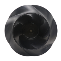
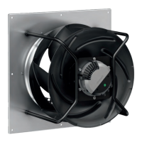
Motor: E15034-85, 3-phase. Nominal Voltage: 400 VAC (range 380-480 VAC), 50/60 Hz. Size: 450 mm. Motor Size: 150. Rotor Surface: Painted black. Electronics Housing Material: Die-cast aluminum. Impeller Material: PP plastic. Support Plate Material: Sheet steel, galvanized. Support Bracket Material: Steel, painted black. Inlet Nozzle Material: ABS plastic. Number of Blades: 5. Direction of Rotation: Clockwise, viewed toward rotor. Degree of Protection: IP55. Insulation Class: "F". Moisture/Environmental Protection Class: H1. Speed: 3430 rpm (preliminary). Power Consumption: 6300 W (preliminary). Current Draw: 9.9 A (preliminary). Min. Ambient Temperature: -40 °C. Max. Ambient Temperature: 40 °C. Installation Position: Shaft horizontal (support struts vertically as illustrated) or rotor on bottom; rotor on top on request. Motor Bearing: Ball bearing. Sound Pressure Level: May exceed 70 dB(A) depending on installation and operating conditions. Touch Current (IEC 60990): <= 3.5 mA. Electrical Hookup: Terminal box. Cable Diameter (min/max):

  • Supply line: 4-10 mm (tightening torque 4 ± 0.6 Nm for M20x1.5), 5-14 mm (tightening torque 6 ±0.9 Nm for M25x1.5).
  • Control/Relay cables: 3 ± 0.3 Nm. Recommended Cable Cross-sections:
  • Supply line: 0.2-6 mm² (rigid), 0.2-6 mm² (flexible), AWG 24-10.
  • Control/Relay cables: 0.2-1.5 mm² (rigid), 0.2-1.5 mm² (flexible), AWG 24-16. Fuses (line protection only):
  • 20A (VDE/UL) for 3/PE AC 380-480 VAC, C20A (automatic circuit breaker).
  • 25A (VDE/UL) for 3/PE AC 380-480 VAC, C25A (automatic circuit breaker).
  • 32A (VDE), 30A (UL) for 3/PE AC 380-480 VAC, C32A (automatic circuit breaker). Maximum Ambient Temperature (operation): 40 °C. Maximum Startup Current: 50 A. Maximum Nominal Voltage Range: 480 V. Ecodesign Regulation (EU) 327/2011 Data:
  • Overall efficiency nes: 73.6% (actual), 59.9% (required 2015).
  • Measurement category: A.
  • Efficiency category: Static.
  • Efficiency grade N: 75.7 (actual), 62 (required).
  • Variable speed drive: Yes.
  • Power consumption Ped: 6.25 kW.
  • Air flow qv: 9985 m³/h.
  • Pressure increase total pfs: 1604 Pa.
  • Speed: 3430 min⁻¹.
  • Specific ratio: 1.02.

Usage Features

Safety:

  • Staff Qualifications: Only suitably qualified, trained, and authorized technical staff may transport, unpack, install, operate, maintain, and use the device. Authorized specialists are required for installation, test runs, and electrical work.
  • Basic Safety Rules: Local industrial safety regulations must be observed. No modifications or additions without ebm-papst approval. Use only approved replacement parts.
  • Electrical Safety: Always connect protective earth first. Live terminals and connections even when switched off. Wait five minutes after disconnecting voltage before opening. In case of fault, rotor and impeller may be energized. Control voltage or stored speed set value can cause automatic restart.
  • Mechanical Safety: Rotating device poses risk of injury; secure against accidental contact. Wait until all parts stop before working. Missing protective devices can lead to ejected parts. Long hair and dangling items can become entangled.
  • Hot Surface: Electronics housing can reach high temperatures; ensure protection against accidental contact.
  • Transport: Transport with care in original packaging to prevent bearing damage or deformation. Secure fan(s) to prevent tipping.
  • Storage: Store in a dry, clean environment, protected from weather and vibration, in original packaging. Recommended storage period is no longer than one year. Maintain storage temperature as per specifications.
  • Mounting: Use appropriate hoisting equipment and lifting devices. Use four round slings passed around the struts of the support bracket. Ensure struts are vertical. Do not exceed 2g acceleration during transport.
  • Electrical Connection: Check nameplate data against connection data. Use cables designed for indicated current level. Protective earth cross-section must be equal to or greater than phase conductor. Recommended 105 °C cables, min AWG 26/0.13 mm². Compliance with EN 61800-5-1 for protective earth contact resistance must be verified.
  • Terminal Box: Strip cables only as far as necessary. Ensure cable gland is sealed and no strain on connections. Use seals in cable gland if necessary. Route supply and control cables separately. Connect protective earth first (tightening torque 3.5 ±0.4 Nm). Ensure wires do not splay out when connecting.
  • Cable Routing: Prevent water ingress into cable gland by routing cable in U-shaped loop or using a drip edge.
  • Switching On/Off: Only switch on if properly installed with all safety mechanisms and electrical hookup. Check for external damage and functional protective devices. Ensure no foreign matter in air flow paths. Apply nominal supply voltage and start by changing input signal. Switch off via control input; do not cycle power supply. Disconnect from power supply for maintenance.
  • Speed Range Suppression: The integrated sensor can measure vibration velocities. Speed ranges with excessive vibration can be blocked out using EC-Control software to prevent continuous operation in resonant ranges.

Improper Use (Prohibited and Hazardous):

  • Operating in an unbalanced state (dirt, ice).
  • Resonant operation or severe vibration.
  • Operation in medical equipment with life-sustaining functions.
  • Conveying solids or abrasive particles in the flow medium.
  • Painting the device.
  • Loose connections during operation.
  • Opening terminal box during operation.
  • Conveying highly corrosive air (unless specifically designed for it).
  • Conveying air with high dust content.
  • Operating near flammable materials or in explosive atmospheres.
  • Using as a safety component or for safety-related functions.
  • Operation with disassembled or manipulated protective devices.

Maintenance Features

General:

  • No repairs by the user; send device to ebm-papst for repair or replacement.
  • If not operated for a lengthy period in dry conditions, start and operate at full speed for one hour every four months.
  • If not operated for a lengthy period in damp conditions (e.g., outdoors), start and operate at full speed for at least three hours once a month to move bearings and evaporate condensate.

Warning/Status Codes:

  • LED on electronics housing indicates motor status with various colors and flash codes (2 Hz frequency, 3-second pause).
  • Green: No warning or fault.
  • Orange: Warning (no user intervention required).
  • Red: Error (at least one error).
  • Multiple simultaneous errors: associated flash codes displayed in succession.
  • Simultaneous warnings and errors: only errors displayed.
  • Warning Codes (LED orange):
    • 1 pulse: Current limitation in action.
    • 2 pulses: Line impedance too high (DC-link voltage unstable).
    • 3 pulses: Power limiter in action.
    • 4 pulses: Output stage temperature high.
    • 5 pulses: Motor temperature high.
    • 6 pulses: Temperature inside electronics high.
    • 7 pulses: DC-link voltage low.
    • 8 pulses: Braking mode: set in case of external drive in opposite direction at high speed for lengthy period (status relay: Yes).
    • 9 pulses: Calibration of rotor position sensor in progress (status relay: Yes).
    • 10 pulses: Actual speed is lower than run monitoring speed limit (status relay: Yes).
    • 11 pulses: Open circuit at analog input or PWM input for the set value (status relay: Yes).
    • 13 pulses: DC-link voltage high.
    • 15 pulses: Line voltage high.
    • 16 pulses: Shake-loose function activated.
  • Status Codes (LED red):
    • 1 pulse: Phase failure or line undervoltage (possible cause: poor power supply quality, missing phase; remedy: check line voltage).
    • 3 pulses: Output stage overheating (possible cause: electronics housing contaminated; remedy: provide better cooling, manual reset required).
    • 4 pulses: Communication error between master controller and slave controller (possible cause: external supply applied via Vout for setting parameters; remedy: switch off line voltage, wait, switch back on).
    • 6 pulses: Motor overheating (possible cause: ambient temperature too high, impermissible operating point; remedy: reduce ambient temperature, correct operating point, manual reset required).
    • 7 pulses: Hall sensor error (possible cause: internal error; remedy: switch off line voltage, wait, switch back on).
    • 8 pulses: Motor blocked (possible cause: mechanical blockage; remedy: switch off, isolate from supply, check freedom of movement of rotor).
    • 9 pulses: Speed limit exceeded.
    • 11 pulses: Rotor position sensor calibration error (possible cause: observe ebm-papst replacement instructions; remedy: rotor position sensor calibration necessary, notify ebm-papst).
    • 13 pulses: DC-link undervoltage (possible cause: line voltage not OK; remedy: check line voltage applied).

Troubleshooting:

  • Impeller not running smoothly: Possible cause: imbalance in rotating parts. Remedy: clean device; replace if imbalance persists. Ensure no weight clips are removed during cleaning.
  • Motor not turning: Possible cause: mechanical blockage. Remedy: switch off, isolate from supply, remove mechanical blockage.
  • Line voltage faulty: Remedy: check line voltage, restore power supply. Error message resets automatically, device restarts automatically without warning.
  • Faulty connection: Remedy: isolate from supply, correct connection; see connection diagram.
  • Broken motor winding: Remedy: replace device.
  • Inadequate cooling: Remedy: improve cooling, allow device to cool down.
  • Ambient temperature too high: Remedy: reduce ambient temperature, allow device to cool down.
  • Impermissible operating point (e.g., back pressure too high): Remedy: correct operating point, allow device to cool down.

Cleaning:

  • Regularly check fans for proper operation and soiling. Adjust frequency of checking based on soiling.
  • Only clean when not in motion. Do not disconnect from power supply; switch off via control input to prevent start-up.
  • Dirt deposits can cause overheating and shorten service life.
  • Severe vibration can destroy the fan; switch off and clean immediately.
  • Preferred method: dry cleaning (e.g., compressed air).
  • Do not use aggressive cleaning agents (acid, alkali, solvent-based).
  • Do not use pointed or sharp-edged objects.
  • Completely remove any cleaning agents used.
  • If severe corrosion is visible on load-bearing or rotating parts, switch off and replace. Repair of load-bearing or rotating parts is not permitted.
  • Operate fan for 2 hours at maximum speed to evaporate any water ingress.
  • If cleaning does not eliminate vibrations, the fan may need rebalancing; contact ebm-papst.

Safety Inspection (every 6 months):

  • Contact protection cover: Visual inspection for intactness or damage. Action: repair or replacement.
  • Device for damage to blades and housing: Visual inspection. Action: replacement.
  • Fastening the cables: Visual inspection. Action: fasten.
  • Insulation of cables for damage: Visual inspection. Action: replace cables.
  • Impeller for wear/deposits/corrosion and damage: Visual inspection. Action: clean impeller or replace device.
  • Tightness of cable gland: Visual inspection. Action: retighten, replace if damaged.
  • Condensation drainage holes for clogging: Visual inspection. Action: open holes.
  • Abnormal bearing noise: Acoustic test. Action: replace device.
  • Vibration test: Vibration tester, start-up or deceleration measurement. Action: clean impeller or replace device.
  • High-voltage test: Test with DC voltage corresponding to the peak value of the AC voltage required by the standard.

Disposal:

  • Disassembly by qualified personnel.
  • Product components are mostly steel, copper, aluminum, and plastic.
  • Separate components for recycling: steel and iron, aluminum, non-ferrous metal (motor windings), plastics (with brominated flame retardants), insulating materials, cables and wires, electronic scrap (circuit boards).
  • Ferrite magnets can be disposed of like normal iron and steel.
  • Contact ebm-papst for further disposal questions.

ebm-papst 8300100075 Specifications

General IconGeneral
Model8300100075
Manufacturerebm-papst
CategoryFan
Fan typeAxial
Voltage24 VDC

Related product manuals