Do you have a question about the ebm-papst 8300100058 and is the answer not in the manual?
Defines hazard levels (DANGER, WARNING, CAUTION, NOTE) for safety information.
Specifies required qualifications for personnel handling the device.
Outlines fundamental safety guidelines for device operation and maintenance.
Highlights the electrical hazard associated with voltage and risk of electric shock.
Details safety requirements for guards and protective devices to prevent injury.
Warns about risks from rotating parts and entanglement of clothing or hair.
Alerts to the risk of burns from hot electronic housings.
Provides guidelines and warnings for safe transportation of the fan.
Specifies permissible uses including power systems, stationary use, and environmental limits.
Lists prohibited and hazardous operating conditions like unbalanced states or conveying solids.
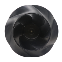
Visual representation of the product with key dimensions and component labels.
Presents detailed technical specifications, electrical data, and performance metrics.
Provides efficiency data compliant with Commission Regulation (EU) 327/2011.
Details materials, size, dimensions, and general technical features of the device.
Specifies requirements for mounting, including screw strength and cable gland data.
Defines maximum permitted ambient temperatures for transport and storage.
Addresses EMC compliance requirements, particularly regarding connection to the public grid.
Provides instructions and precautions for physically connecting the device.
Detailed guidance on making electrical connections, including safety warnings.
Specifies checks before connection, including nameplate data and power supply matching.
Details cable cross-sections, fuse assignments, and protective earth requirements.
Explains reactive currents caused by the EMC filter and their typical values.
Guidance on selecting and using residual current devices (RCDs).
Instructions for preparing and connecting cables within the terminal box.
Details on stripping cables and ensuring proper sealing and strain relief.
Provides data for connecting supply lines and control/relay cables.
Step-by-step instructions for connecting cables to terminals, including safety.
Recommendations for routing cables to prevent moisture penetration into the terminal box.
Details the function and assignment of each terminal on the device.
Details configurable I/O options, electrical specifications, and MODBUS registers.
Illustrates equivalent circuit diagrams for various hardware inputs and outputs.
Shows equivalent circuit diagrams for RS485 bus connections.
Instructions and safety precautions for powering up the device.
Procedures for switching the device off during operation or for maintenance.
Details integrated functions that automatically switch off the motor during specific faults.
Safety warnings regarding live terminals and automatic restart during maintenance.
Lists common malfunctions, possible causes, and remedies for troubleshooting.
Explains the LED indicators and flash codes for motor status and warnings.
Details status codes indicated by the LED, including cause and remedy.
Describes manual vibration testing methods and frequency for fans.
Safety warnings about rotating fans during cleaning and notes on damage prevention.
Addresses bearing replacement necessity and adapting maintenance for dust exposure.
Details items to check, how to check, frequency, and required actions for safety inspection.
Outlines procedures for disassembly and guidance on separating components for recycling.
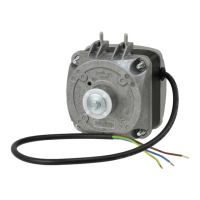
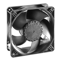
This document provides operating instructions for the ebm-papst VBH0400CTRNS device, an integrated fan designed for air conveyance.
The VBH0400CTRNS is a built-in device exclusively designed for conveying air according to its technical specifications. It operates in power systems with grounded neutral (TN/TT), phase conductor grounding, or IT power systems, and is intended for use in networks with quality characteristics as per EN 50160. The device supports stationary operation and performs all necessary maintenance work. It conveys air at ambient air pressure between 800 mbar and 1050 mbar, within a permitted ambient temperature range. The fan is equipped with integrated protective functions that automatically switch off the motor in case of faults such as rotor position detection error, blocked rotor, line undervoltage, or phase failure. It features an alarm relay and configurable inputs/outputs (I/O), MODBUS V6.3, motor current limitation, RS-485 MODBUS-RTU, and a soft start function. A voltage output (3.3-24 VDC) is available for external devices. The control interface operates with SELV potential, safely disconnected from the mains. Thermal overload protection for electronics/motor, line undervoltage/phase failure detection, and a vibration sensor are also integrated.
The device is designed for easy installation, with specific instructions for mechanical and electrical connections. It is crucial to ensure proper handling during transport and installation to prevent damage to bearings, frame, or impeller. The fan should be secured against accidental contact and vibration. When connecting to air ducts, vibration isolation (e.g., compensators) is recommended. The terminal box provides clear connections for supply, control, and relay cables, with specified cross-sections and fuse requirements. Cable routing should prevent water ingress into the cable glands, ideally by forming a U-shaped loop. The device's control lines should be routed separately from the supply line with a clearance of at least 10 cm to prevent malfunctions. The integrated EMC filter may cause reactive currents in the supply line, typically < 500 mA, even when the motor is at a standstill. The effective power in this operational readiness state is typically < 6 W. The device is a built-in component and lacks a disconnecting switch, requiring connection to circuits that can be switched off with an all-pole disconnection switch.
Regular maintenance is essential for a long service life. This includes checking the fan for proper operation and soiling, with frequency adapted to the degree of soiling. Cleaning should only be performed when the device is not in motion, and it should not be disconnected from the power supply; rather, it should be switched off via the control input to prevent accidental start-up. Dry cleaning, such as using compressed air, is the preferred method. Aggressive cleaning agents, acids, alkalis, solvents, or sharp objects should not be used. If severe corrosion is visible on load-bearing or rotating parts, the device should be switched off and replaced. Repair of such parts is not permitted. After cleaning, the fan should be operated at maximum speed for 2 hours to evaporate any ingressed water. If cleaning does not eliminate vibrations, rebalancing may be necessary. The fan is equipped with maintenance-free ball bearings designed for a service life of 40,000 hours.
A "manual" vibration test should be performed every 6 months, across the fan's entire speed range, if the integrated vibration sensor is not used. Speed ranges with excessive vibration velocities (e.g., due to resonances or imbalances) must be avoided in continuous operation. The integrated sensor can measure vibration velocities, and EC-Control software allows blocking out these problematic speed ranges. The LED on the electronics housing provides warning/status codes through various colors and flash patterns (2 Hz frequency, 3-second pause between codes) to indicate motor status (Green: no warning/fault, Orange: warning, Red: error). Manual reset for certain errors (e.g., phase failure, line undervoltage) involves switching off the line voltage, waiting briefly, and then switching it back on, or using the "Fan enable/disable" input.
For long-term storage, the device should be stored in a dry, vibration-free, clean environment, protected from weather, and in its original packaging. It is recommended to store the device for no longer than one year. If the device is not operated for a lengthy period in installed condition in a dry environment, it should be started up and operated at full speed for one hour at least every four months. In damp environments (e.g., outdoors), this should be done for at least two hours once a month to move the bearings and evaporate any condensate.
Disposal must comply with country-specific legal regulations and standards. Disassembly should be performed or supervised by qualified personnel, separating components into categories such as steel/iron, aluminum, non-ferrous metal (motor windings), plastics (especially with brominated flame retardants), insulating materials, cables/wires, and electronic scrap. Ferrite magnets can be disposed of like normal iron and steel.