Chengdu Ebyte Electronic Technology Co,;Ltd
Copyright @2012–2023,
Chengdu Ebyte Electronic Technology Co,;Ltd
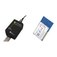
Step 1 Hardware preparation
Prepare the following items:
Debugger/Programmer CC Debugger https://www.ebyte.com/en/product-view-news.html?id=947
Ebyte E18 seires module or E18 series test kits https://www.cdebyte.com/product_serch/E18-/1/
Step 2 Install tools and drivers
To obtain the USB drivers required by the tools, it is recommended to download and install the tools listed below:
SmartRF™ Flash Programmer https://www.ti.com/tool/FLASH-PROGRAMMER
After the tool is installed, the driver will be stored in the following default path:
C:\Program Files\Texas Instruments\SmartRF Tools\Drivers\cebal
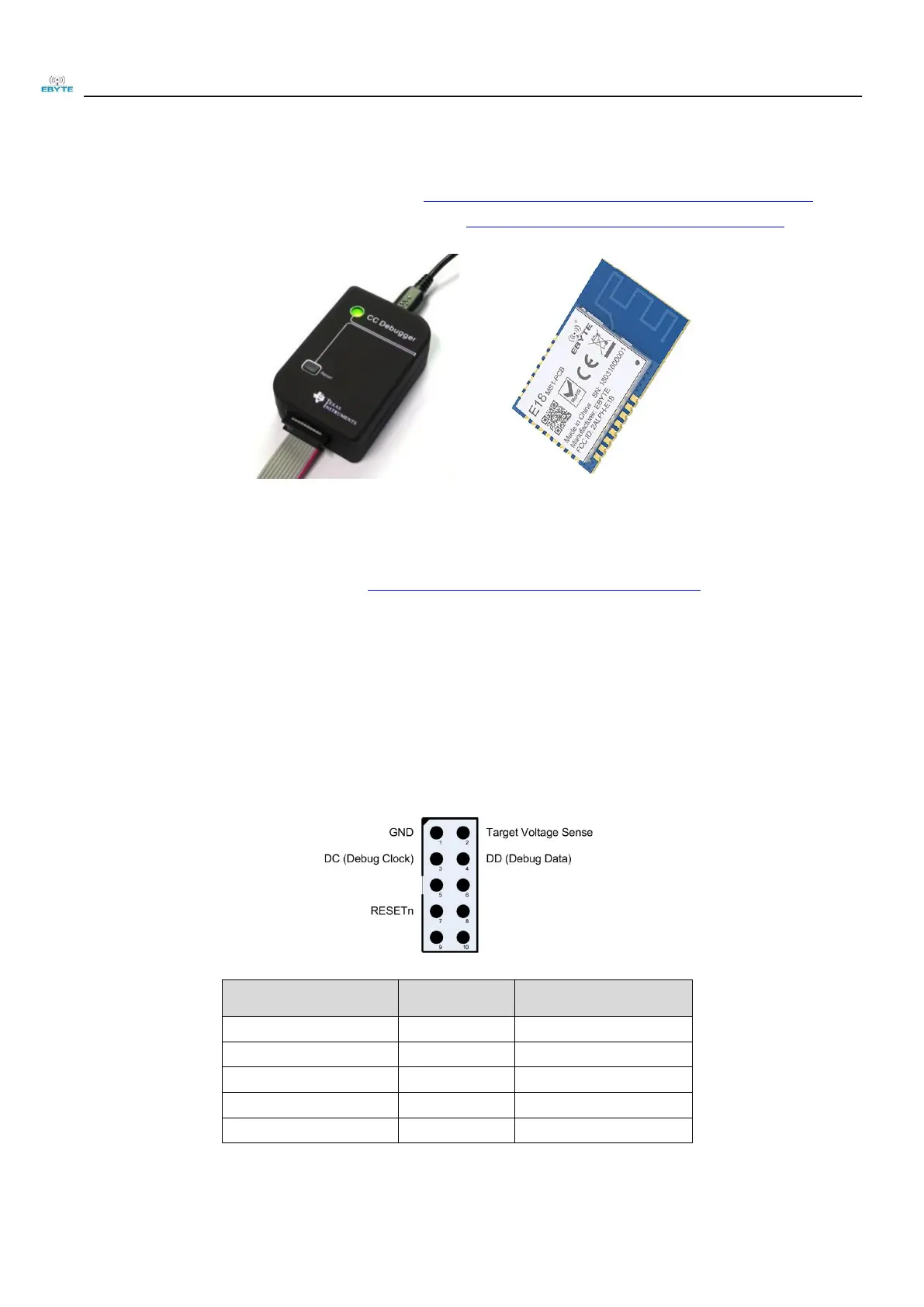
Step 3 Connect debugger/programmer to target module/test kit
Connect debugger/programmer to target module/test kit,The minimum connections required for SOC debugging and
programming are shown in the below:
For the pin definitions of E18 series modules/test kits, please refer to the relevant product manuals.
 Loading...