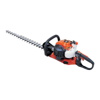
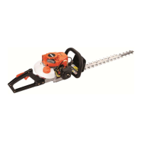
HCR-1510
4
SERVICE INFORMATION
1-3 Torque limits
Descriptions Size kgf•cm N•M in•lbf
Starter Pawl assembly M 8 160 - 200 16 - 20 140 - 175
system
Starter case M 4* 14 - 28 1.4 - 2.8 12 - 24
Ignition Ignition coil M 4 35 - 50 3.5 - 5.0 30 - 45
system
Spark plug M 14 150 - 170 15 - 17 130 - 150
Fuel Carburettor M 5 25 - 40 2.5 - 4.0 22 - 35
system
Intake insulator M 5* 25 - 40 2.5 - 4.0 22 - 35
Fuel tank M 5* 30 - 45 3.0 - 4.5 26 - 40
Clutch Clutch hub M 8 160 - 200 16 - 20 140 - 175
Clutch case M 4* 30 - 50 3 - 5 26 - 45
Engine Crankcase M 5** 70 - 110 7 - 11 60 - 95
Cylinder M 5** 70 - 110 7 - 11 60 - 95
Muffler M 5 60 - 100 6 - 10 50 - 90
Cylinder cover M 4* 14 - 28 1.4 - 2.8 12 - 24
Gear Gear case M 5 50 - 70 5 - 7 45 - 60
case Bottom cover M 4 30 - 50 3 - 5 26 - 45
Cutter Cutter bolts (See NOTE below) M 6 10 - 15 1.0 - 1.5 9 - 13
Cutter support M 6* 45 - 75 4.5 - 7.5 40 - 65
Handle Rear handle set to
M 5* 25 - 40 2.5 - 4.0 22 - 35
handle fixture
Front handle M 5 30 - 45 3.0 - 4.5 26 - 40
Regular bolt, nut and screw
M 3 6 -10 0.6 - 1.0 5 - 9
M4 15 -25 1.5 - 2.5 13 - 22
M 5 25 -45 2.5 - 4.5 22 - 40
M 6 45 -75 4.5 - 7.5 40 - 65
M 8 110 -150 11 - 15 95 - 130
* Apply thread locking sealant (See next page).
** The torque differences among 2 bolts should not exceed 20 kgf•cm (2Nm, 17in•lbf) on one cylinder or
crankcase.
NOTE : To adjust cutter clearance, fasten all cutter bolts to this torque, then back 1/2 turns (180°) Anticlockwise.
 Loading...

