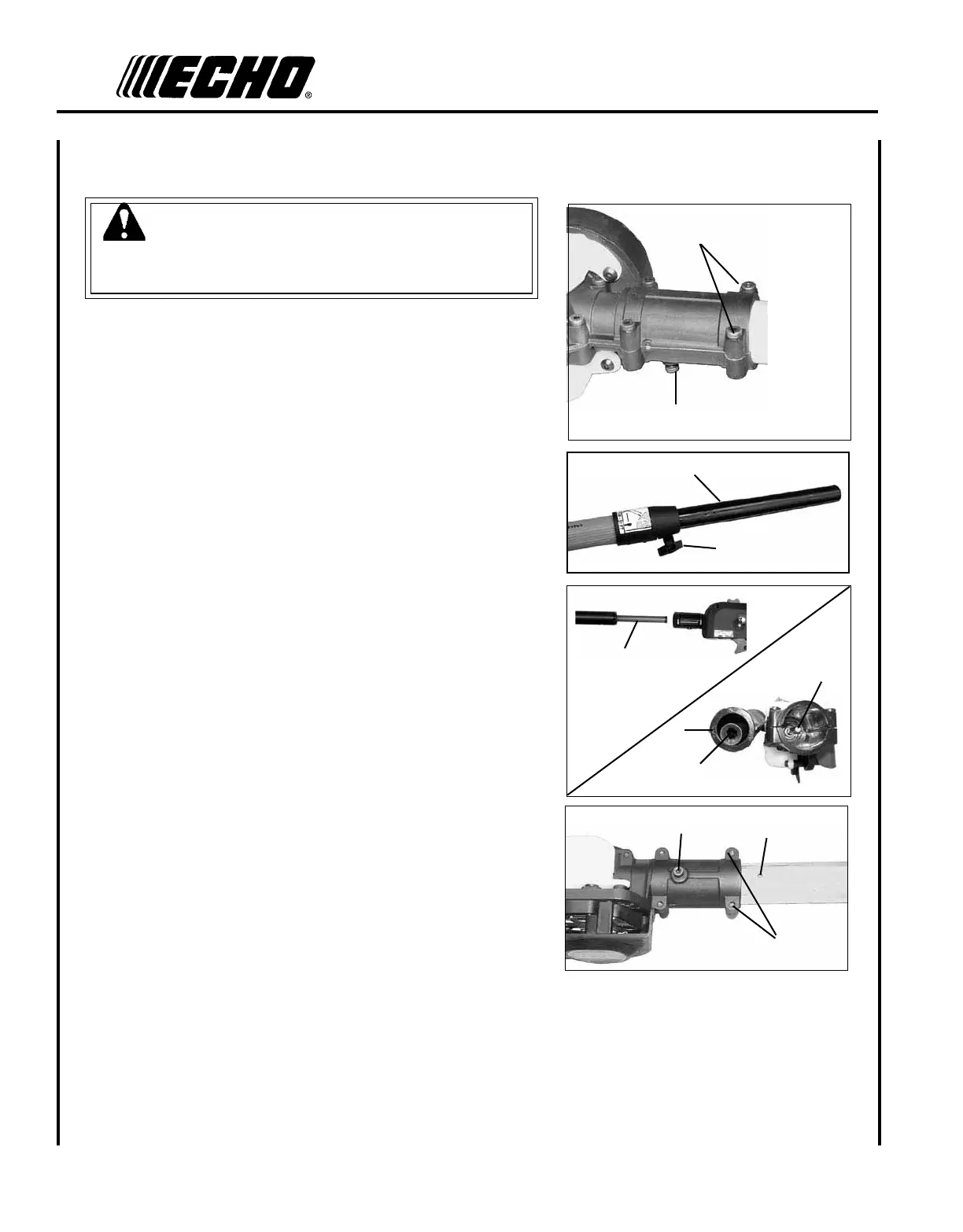
12
WARNING
6DZ&KDLQLVVKDUS$OZD\VZHDUJORYHVZKHQKDQGOLQJDVVHPEO\
otherwise serious personal injury may result.
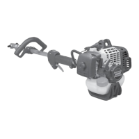
1. Loosen the two (2) screws (C) and remove locator screw (D) on
cutting attachment.
2. Loosen clamp knob (E) turning counter clockwise.
3XOOXSSHUWXEH)RXWRI¿EHUJODVVORZHUWXEHPP
LQWKHQVOLGH)EDFNLQWR¿EHUJODVVORZHUWXEHH[SRVLQJLQQHU
drive shaft (G). Align and join star shaped drive end of inner drive
shaft (G) with cutting attachment shaft (H).
$OLJQULGJHV-RQXSSHUWXEHZLWKVHDPVLQFXWWLQJDWWDFKPHQW
5. Slide together aligning locator screw hole (D) in cutting attachment
with locating hole (I) in upper tube.
6. Install locator screw (D) and tighten. Tighten two (2) cutting at-
tachment screws (C).
7. Extend upper tube to desired length. Tighten center clamp knob (E)
turning clockwise.
D
C
CUTTING ATTACHMENT TO DRIVE SHAFT INSTALLATION
C
I
G
H
G
J
E
F
D